Disk brake

Active Publication Date: 2011-12-01
HITACHI ASTEMO LTD
View PDF4 Cites 5 Cited by
  • Summary
  • Abstract
  • Description
  • Claims
  • Application Information

AI Technical Summary

Benefits of technology

[0020]According to the aspects of the present invention,

Problems solved by technology

Therefore, the guide attachment part may be rapidly coagulated when the caliper is cast, a

Method used


Image

  • Disk brake
  • Disk brake
  • Disk brake

Examples


Example

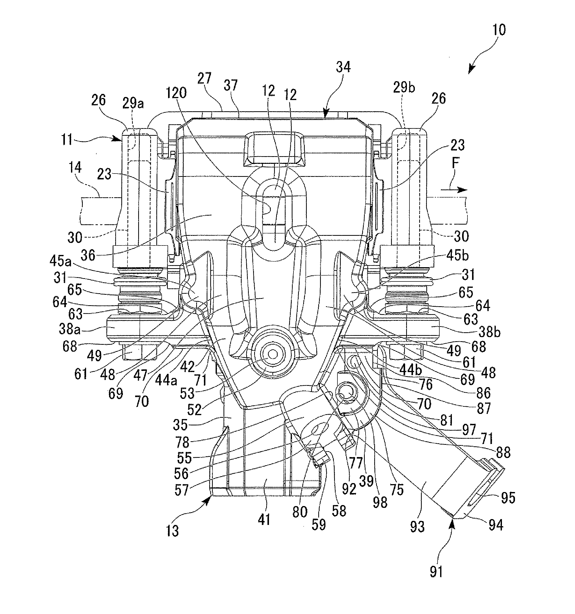
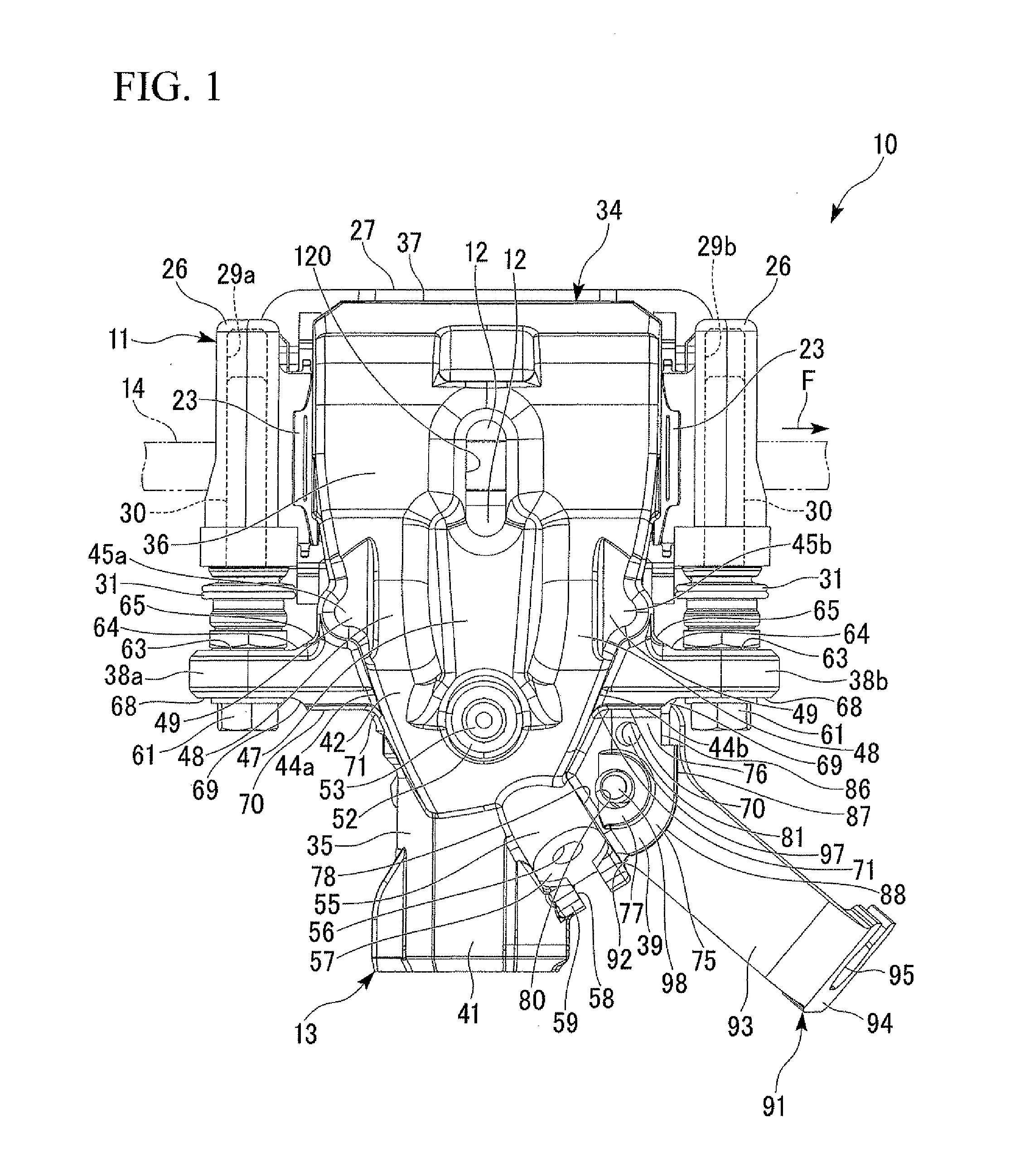
[0031]Hereinafter, an embodiment of the present invention will be described with reference to the accompanying drawings. A disk brake 10 in accordance with an embodiment shown in FIGS. 1 to 5 includes a carrier (an attachment member) 11, a pair of friction pads 12, and a caliper 13.

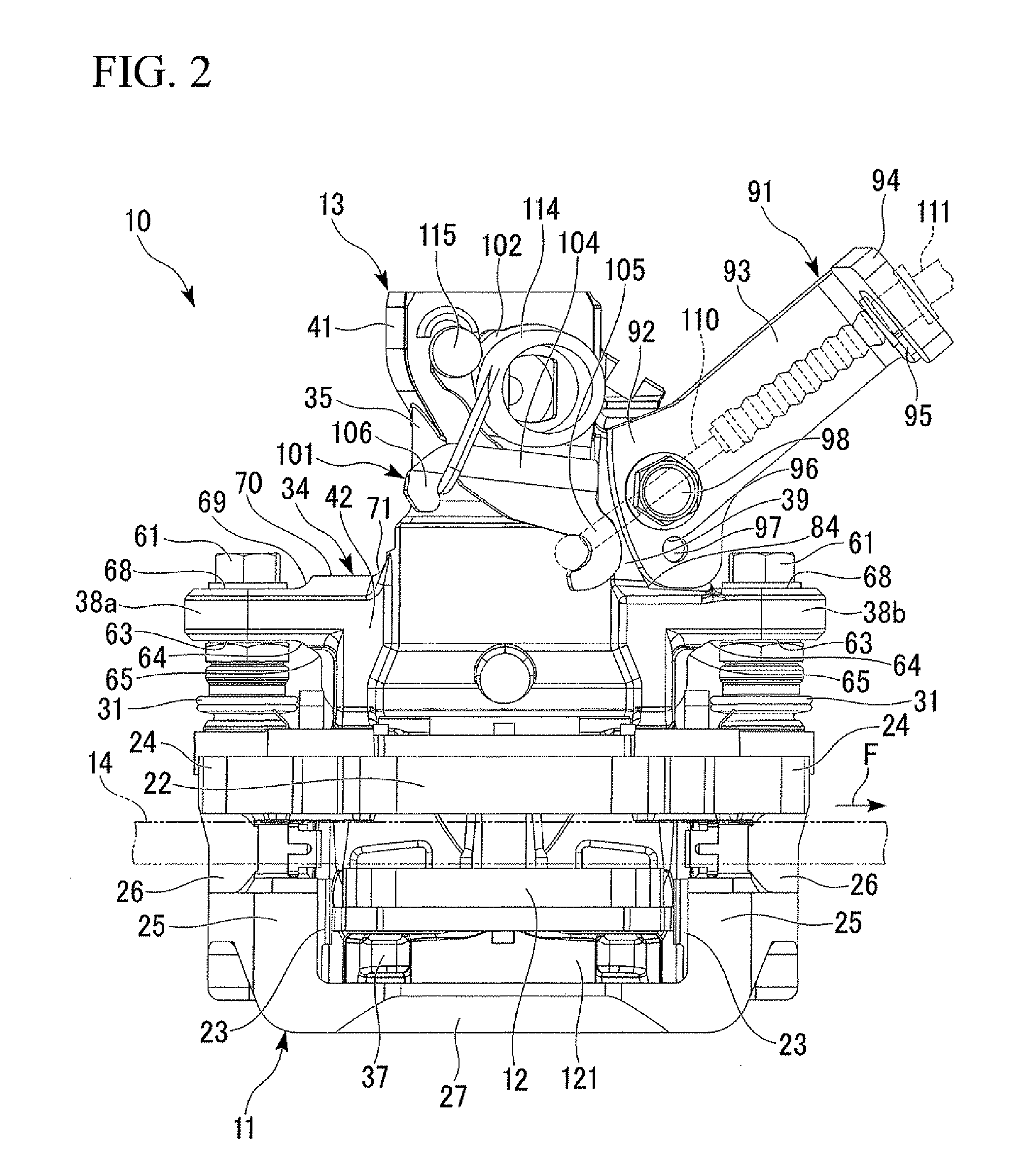
[0032]As shown in FIGS. 1 and 2, the carrier 11 is disposed to be astride an outer diameter side of a disk 14 rotated with a wheel (not shown), which is to be braked, and fixed to a non-rotation part of a vehicle (not shown). The pair of friction pads 12 are disposed on both sides of the disk 14 via the disk 14. The friction pads 12 are supported by the carrier 11 to be slidable in an axial direction of the disk 14 in a state in which the friction pads 12 are disposed at both surfaces of the disk 14 to oppose each other. The caliper 13 is supported by the carrier 11 to be slidable in the axial direction of the disk 14 in a state in which the caliper 13 is astride the outer diameter side of the disk 14. Th...


PUM


Abstract

Provided is a disk brake having a caliper. The caliper includes a cylinder part disposed at one side in a disk axial direction and having a bore for accommodating a piston, a pair of arm parts extending to both sides of the cylinder part in a disk rotational direction and having ends to which sliding pins are fixed, and a guide attachment part configured to couple the one arm part to the cylinder part and to which a cable guide member is fixed, which are integrally formed with each other. A thickness of the guide attachment part in a disk diameter direction and a thickness of the one arm part in the disk diameter direction at least partially overlap in the disk axial direction.

Description

BACKGROUND OF THE INVENTION[0001]1. Field of the Invention[0002]The present invention relates to a disk brake.[0003]Priority is claimed on Japanese Patent Application No. 2010-125196 filed on May 31, 2010, the content of which is incorporated herein by reference.[0004]2. Description of Related Art[0005]A caliper having a parking brake mechanism includes a cable guide member configured to hook a cable including a wire for pulling a lever (For example, Japanese Unexamined Patent Application, First Publication No.: 2005-291277). A guide attachment part configured to attach the cable guide member to the caliper is integrally formed with the caliper when the caliper is cast.[0006]The guide attachment part projects from the caliper. Therefore, the guide attachment part may be rapidly coagulated when the caliper is cast, and the molten metal fluidity may be deteriorated, degrading the formability of the caliper.SUMMARY OF THE INVENTION[0007]An object of the present invention is to provide ...

Claims


Application Information

Patent Timeline
IPC IPC(8): F16D55/22F16D65/18
CPCF16D55/226F16D55/2265F16D65/18F16D2125/64F16D2121/14F16D2123/00F16D2125/60F16D2121/02
Inventor MIURA, YORIHITONAKAYAMA, SHINICHITAKAHASHI, KATSUHIRO
Owner HITACHI ASTEMO LTD
Why Eureka
Try Eureka