Manufacturing method of honeycomb structure, and honeycomb structure

Active Publication Date: 2018-08-02
NGK INSULATORS LTD
View PDF3 Cites 2 Cited by
  • Summary
  • Abstract
  • Description
  • Claims
  • Application Information

AI Technical Summary

Benefits of technology

[0028]In a manufacturing method of a honeycomb structure of the present invention, a slurry which contains a cordierite forming raw material in the same manner as in the honeycomb formed body and has a porosity after firing which is higher than a porosity of a honeycomb structure main body as much as 5% or more is coated on specific regions of a circumferential surface of a honeycomb formed body. Consequently, there are strengthened the specific regions of a circumferential wall of the honeycomb formed body in which cracks are easily generated during the firing, and it is possible to manufacture the honeycomb structure without generating any cracks in the regions. Furthermore, it is not necessary to limit an amount of an additive (an organic binder or the like) to be added to a raw material for the purpose of improving formability, and hence the formability is not adversely affected. Additionally, it is not necessary to add an inorganic binder to the raw material, and hence characteristics of the honeycomb structure are not deteriorated or production cost is not raised by the inorganic binder. In addition, even when a heat curve during the firing is not adjusted (prolonged) or the number of the honeycomb formed bodies to be packed in a kiln (

Problems solved by technology

However, even in a method of adjusting (prolonging) a heat curve during firing, it is difficult to sufficiently inhibit generation of cracks.
Furthermore, in the method of adjusting (prolonging) the heat curve during the firing or a method of decreasing the number of honeycomb formed bodies to be packed in a kiln (a firing furnace), there has been the problem that productivity deteriorates.
Additionally, in a method of limiting an amount of an additive to be added to a raw material, there has been the problem tha

Method used


Image

  • Manufacturing method of honeycomb structure, and honeycomb structure
  • Manufacturing method of honeycomb structure, and honeycomb structure
  • Manufacturing method of honeycomb structure, and honeycomb structure

Examples


example 1

[0088]As cordierite forming raw materials, alumina, aluminum hydroxide, kaolin, talc and silica were used. To 100 parts by mass of cordierite forming raw material, 1 mass part of pore former, 32 parts by mass of dispersing medium, 6 parts by mass of organic binder and 1 part by mass of dispersing agent were added, mixed, and kneaded to prepare a kneaded material. As the dispersing medium, water was used, and as the pore former, a foamable resin having an average particle diameter of 40 μm was used. As the organic binder, hydroxypropyl methylcellulose was used, and as the dispersing agent, ethylene glycol was used.

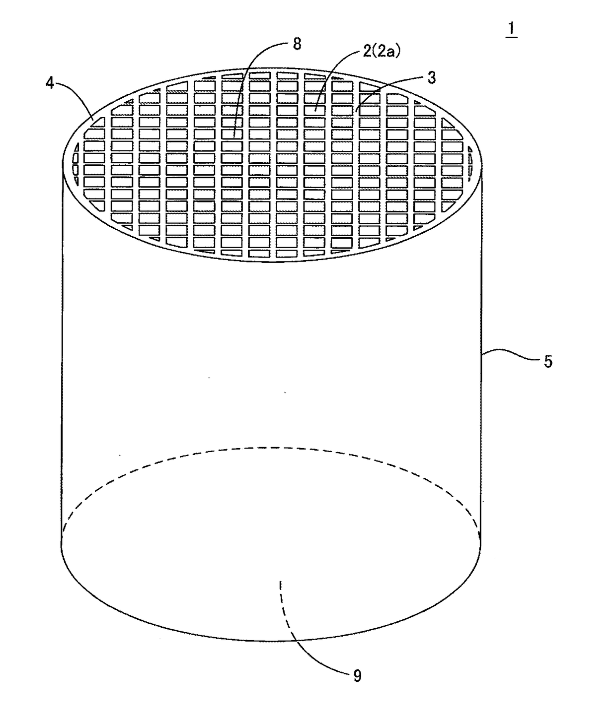
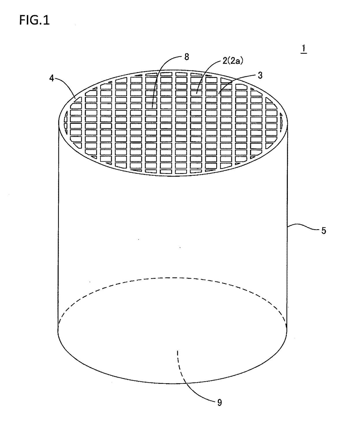
[0089]Next, the kneaded material was extruded by using a predetermined die, to form a honeycomb formed body having partition walls defining a plurality of cells extending from one end face to the other end face, and a circumferential wall surrounding the partition walls. In this honeycomb formed body, the whole shape was a round pillar shape, and the plurality of cells was ...

examples 2 to 4

[0099]The procedure of Example 1 was repeated except that a value x was changed to a value shown in Table 1, to prepare honeycomb structures. As to the obtained honeycomb structures, evaluation was performed on criteria similar to those of Example 1. Table 1 shows the evaluation results.

examples 5 to 8

[0100]The procedure of Example 2 was repeated except that a slurry was coated so that a thickness of a coating layer formed by the slurry through firing was a thickness shown in Table 1, to prepare honeycomb structures. As to the obtained honeycomb structures, evaluation was performed on criteria similar to those of Example 1. Table 1 shows the evaluation results.


PUM

PropertyMeasurementUnit
Fractionaaaaaaaaaa
Thicknessaaaaaaaaaa
Thicknessaaaaaaaaaa

Abstract

A manufacturing method of a honeycomb structure includes a forming step of forming a honeycomb formed body by use of a kneaded material containing a cordierite forming raw material, a slurry coating step of coating a coating layer forming slurry which contains a cordierite forming raw material on four regions in a rotation area when each of two straight lines passing through the center of gravity of the cross section and extending in a diagonal direction of main quadrangular cells is rotated in a range of ±x° of the center of gravity in a circumferential surface, and a firing step of firing the honeycomb formed body on which the slurry is coated. The value x is in a range of 7 to 45, and the slurry is adjusted so that the coating layer has a porosity higher than that of the honeycomb structure body as much as 5% or more.

Description

[0001]“The present application is an application based on JP-2017-016351 filed on Jan. 31, 2017 with Japan Patent Office, the entire contents of which are incorporated herein by reference.”BACKGROUND OF THE INVENTIONField of the Invention[0002]The present invention relates to a honeycomb structure for use in a catalyst carrier for an exhaust gas purifying catalyst converter, a particulate trapping filter such as a diesel particulate filter or a gasoline particulate filter, or the like, and a manufacturing method of the honeycomb structure.Description of the Related Art[0003]Honeycomb structures are broadly used in a catalyst carrier for an exhaust gas purifying catalyst converter of an internal combustion engine such as a car engine, particulate trapping filters such as a diesel particulate filter (DPF) and a gasoline particulate filter (GPF), and the like.[0004]In the case of manufacturing such a honeycomb structure, a kneaded material including a predetermined ceramic raw material...

Claims


Application Information

Patent Timeline
IPC IPC(8): C04B38/00B01J29/88B01J35/04B01J37/00B01J37/02B01J37/08C04B41/00C04B41/50C04B41/87B01D46/24B01D46/00
CPCC04B38/0009B01J29/88B01J35/04B01J37/0009B01J37/0215B01J37/08C04B41/009C04B41/5024C04B41/87B01D46/247B01D46/0001B01D46/2429B01D2046/2433B01D2046/2481B01D46/2474B01D2046/2485B01D39/2068B01D46/00B01D46/2418B28B11/04C04B35/195C04B38/0006F01N3/0222F01N3/2828F01N2330/04F01N2330/06B01D2258/01B01D2239/10B01D46/2482B01D46/2494C04B38/0074C04B2111/00793C04B2111/0081C04B41/85C04B41/4582C04B41/4539C04B41/4572
Inventor KITAGUCHI, DANIEL YUKICHIKASHIWAGI, NOBUYUKI
Owner NGK INSULATORS LTD
Why Eureka
Try Eureka