Electric machine rotor bar and method of making same

a technology of electric machines and rotor bars, which is applied in the direction of rotors, cage rotors, synchronous motors, etc., can solve the problems of more expensive copper rotor bars than aluminum rotor bars

Active Publication Date: 2011-12-01
GENERAL ELECTRIC CO
View PDF12 Cites 20 Cited by
  • Summary
  • Abstract
  • Description
  • Claims
  • Application Information

AI Technical Summary

Problems solved by technology

For example, rotor bars are often made of aluminum because of its electrical properties and the costs associated with “working” aluminum.
However, due to the high melting point of copper, as compared to aluminum, and the difficulties associated with working with copper, copper rotor bars tend to be more costly than aluminum rotor bars.

Method used


Image

  • Electric machine rotor bar and method of making same
  • Electric machine rotor bar and method of making same
  • Electric machine rotor bar and method of making same

Examples


Embodiment Construction

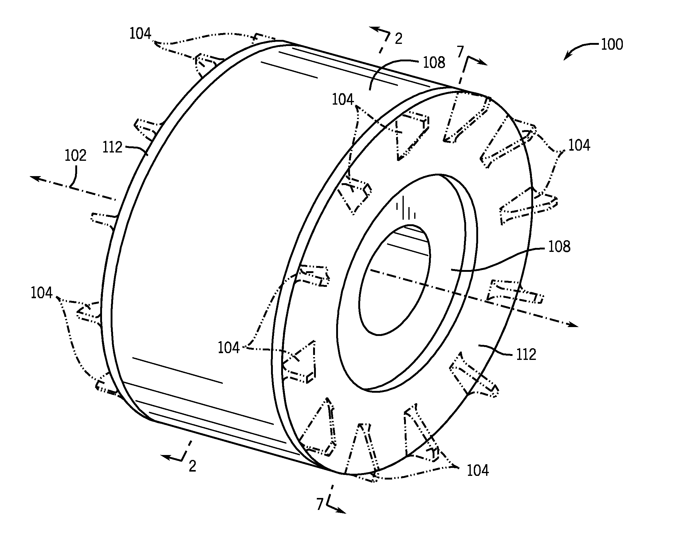
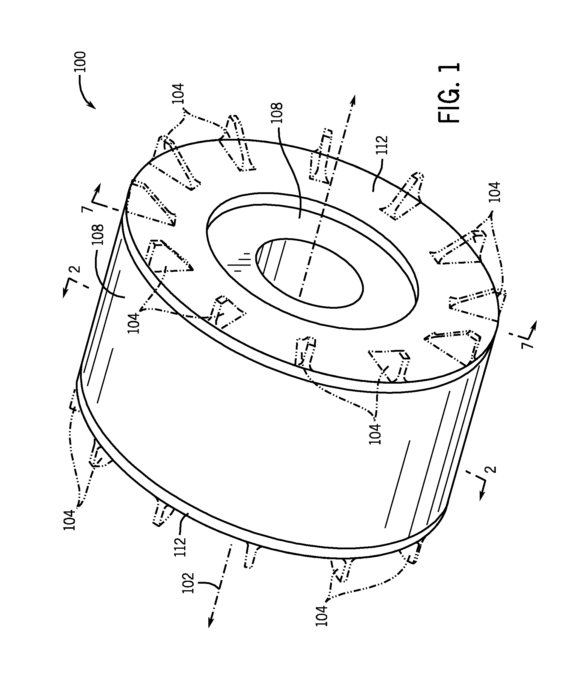
[0020]Referring to FIG. 1, a diagram a portion of an electric machine 100 is shown according to an embodiment of the invention. According to the embodiment of FIG. 1, electric machine 100 has an axis of rotation 102 about which it rotates. Though not shown, but as would be appreciated by those skilled in the art, a shaft along axis of rotation 102 would, once rotated, cause electric machine 100 to rotate. It is contemplated that electric machine 100 may include a plurality of cooling fins 104 (shown in phantom). Embodiments without cooling fins 104 or with a greater or lower number of cooling fins than those shown in FIG. 1 are, however, envisioned.

[0021]It is also contemplated electric machine 100 may be of any type of electric machine that employs rotor bars. For example, such electric machines may include an induction machine such as an induction motor or generator. However, and more generally, such an electric machine may also include electric motors, generators, or the like. As...


PUM

PropertyMeasurementUnit
frequencyaaaaaaaaaa
electrical resistivityaaaaaaaaaa
metallicaaaaaaaaaa

Abstract

A method, system, and apparatus including an electric machine having a plurality of rotor bars and a first coupling component configured to electrically couple the plurality of rotor bars together. Each rotor bar of the plurality of rotor bars includes a first metallic material having a first electrical resistivity and a second metallic material cast about the first material, where the second metallic material has a second electrical resistivity greater than the first electrical resistivity. The first metallic material has a first end and a second end opposite the first end and the first coupling component is coupled to the first end of the first metallic material.

Description

BACKGROUND OF THE INVENTION[0001]Embodiments of the invention relate generally to electric machine rotor bars and, more particularly, to a bi-metallic electric machine rotor bar.[0002]Often, rotor bars of an electric machine such as an electric motor or generator are manufactured of one material. For example, rotor bars are often made of aluminum because of its electrical properties and the costs associated with “working” aluminum.[0003]It has been found that the running efficiency of an electric machine can often be increased by decreasing the electrical resistance of the respective rotor bars. In other words, an electric machine having rotor bars with lower electrical resistance tends to operate more efficiently than a comparable electric machine having rotor bars with a higher electrical resistance (i.e., as rotor bar resistance decreases the electric machine running efficiency often increases).[0004]To exploit this relationship between rotor bar resistance and running efficiency...

Claims


Application Information

Patent Timeline
Patent Type & Authority Applications(United States)
IPC IPC(8): H02K17/16
CPCB22D19/0054Y10T29/49012H02K15/0012H02K3/12
Inventor ALEXANDER, JAMES P.KING, ROBERT DEANEL-REFAIE, AYMAN MOHAMED FAWZI
Owner GENERAL ELECTRIC CO
Why Eureka
Try Eureka