Package manufacturing method, package, piezoelectric vibrator, oscillator, electronic device and radio timepiece

a piezoelectric vibrator and piezoelectric technology, applied in the direction of caps, liquid handling, and closures using stoppers, can solve the problems of difficult to ensure the thickness of each electrode, difficult to form a cavity, gap between the core portion and the through hole, etc., to achieve excellent air tightness, improve quality, and high quality

Inactive Publication Date: 2011-12-01
SEIKO INSTR INC
View PDF8 Cites 2 Cited by
  • Summary
  • Abstract
  • Description
  • Claims
  • Application Information

AI Technical Summary

Benefits of technology

[0035]According to the oscillator, the electronic device and the radio timepiece that are described above, since the above-described piezoelectric vibrator is provided, it is possible to similarly improve the quality.
[0036]With the package manufacturing method according to the invention, it is possible to manufacture the high quality package in which air bubble formation inside the glass frit is suppressed while airtightness in the cavity is ensured.
[0037]Further, the package according to the invention has excellent airtightness and improved quality.
[0038]Further, since the piezoelectric vibrator, the oscillator, the electronic device and the radio timepiece according to the invention are provided with the above-described package, it is possible to similarly improve the quality.

Problems solved by technology

However, with this method, there is a possibility that a gap is formed between the core portion and the through hole.
Therefore, it is difficult to ensure airtightness in a cavity formed between the base substrate and the lid substrate.
When the routing electrodes, the external electrodes and the like are formed on the base substrate in a state in which the recessed portion remains in the glass frit, it is difficult to form each of the electrodes to have a uniform thickness, and there is a case in which the electrode is formed with a section whose thickness is considerably thin.
In this case, there is a risk that the thin section formed in each of the electrodes is locally disconnected due to deterioration over time or the like, and there is a possibility that conductivity between the piezoelectric vibrating reed and the external electrodes is impaired.
Further, even when the head portion of the rivet is not removed after firing the glass frit, there is a risk that a crack or chip is generated due to the air bubble formed inside the glass frit.

Method used


Image

  • Package manufacturing method, package, piezoelectric vibrator, oscillator, electronic device and radio timepiece
  • Package manufacturing method, package, piezoelectric vibrator, oscillator, electronic device and radio timepiece
  • Package manufacturing method, package, piezoelectric vibrator, oscillator, electronic device and radio timepiece

Examples


first embodiment

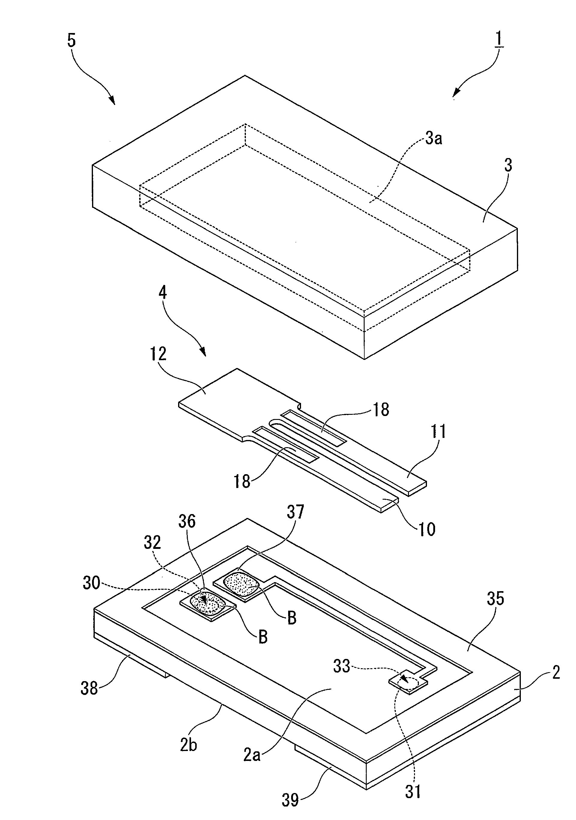
[0071]Next, a first embodiment according to the invention will be described with reference to FIG. 1 to FIG. 26. Note that, in the embodiment, a case in which a package is adopted as a piezoelectric vibrator will be described as an example.

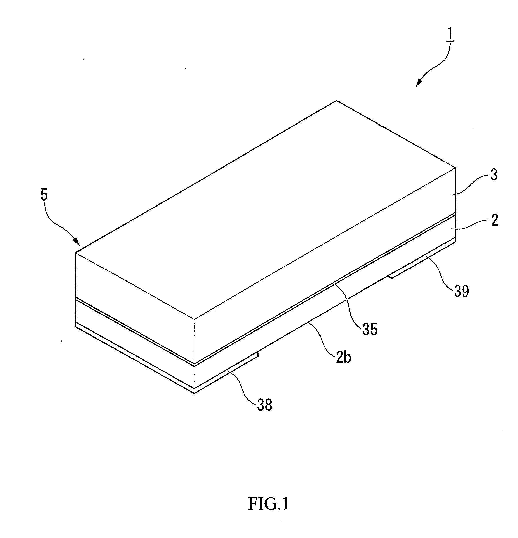
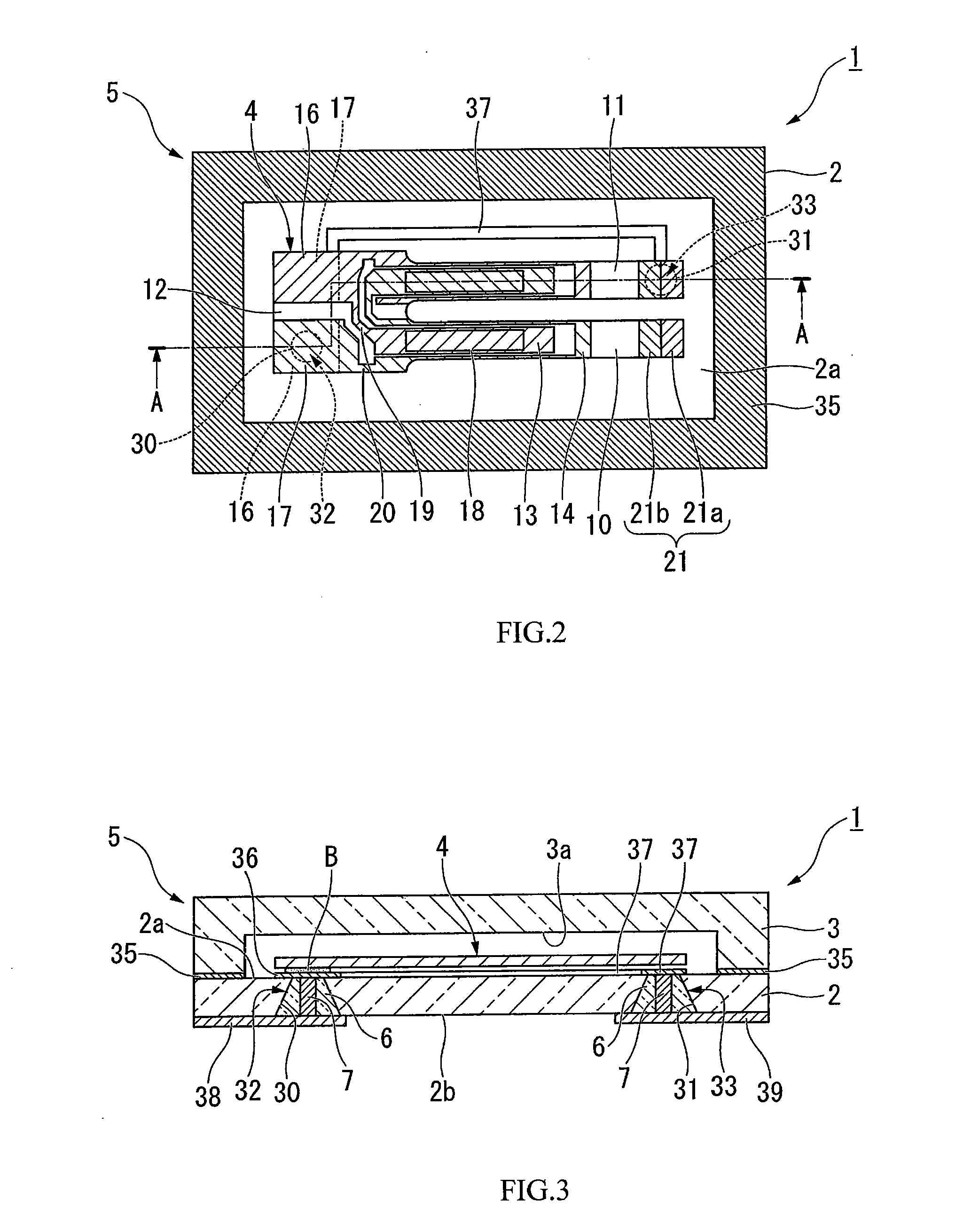
[0072]As shown in FIG. 1 to FIG. 4, a piezoelectric vibrator 1 of the embodiment is of a surface mount type (a two layer structure type), and includes: a package 5 that is formed such that a base substrate 2 and a lid substrate 3 (a pair of substrates) are laminated and bonded to each other; and a piezoelectric vibrating reed (an object to be housed) 4 that is housed, in an airtightly sealed state, in a cavity C that is formed inside the package 5 by being sandwiched between the base substrate 2 and the lid substrate 3.

(Piezoelectric Vibrating Reed)

[0073]As shown in FIG. 5 to FIG. 7, the piezoelectric vibrating reed 4 is a tuning-fork type vibrating reed formed of a piezoelectric material, such as crystal, lithium tantalate, lithium niobate or the...

second embodiment

[0142]Next, a second embodiment according to the invention will be described based on FIG. 27 to FIG. 29.

[0143]Note that, in the second embodiment, structural members that are the same as those of the first embodiment are denoted with the same reference numerals and a description thereof is omitted, and only different points will be described.

[0144]As shown in FIG. 27 to FIG. 29, in a piezoelectric vibrator 80 according to the embodiment, the head portion (the flat plate portion) 8 that is connected to the core portion 7 and is disposed in the cavity C is provided in a package 81. As shown in FIG. 28, the head portion 8 is disposed in the cavity C so as to cover each of the through holes 30, 31. In other words, in the embodiment, the head portion 8 of the rivet 9 is not polished and is left in the cavity C.

[0145]Further, while the head portion 8 is disposed to cover each of the through holes 30, 31, the glass frit 6 is exposed in the cavity C. In the example shown in the drawing, th...


PUM


Abstract

This package manufacturing method is a method for manufacturing a package using a rivet having a flat plate-shaped head portion and a core portion protruding from a rear surface of the head portion. The package includes: a plurality of substrates that are bonded to each other: a cavity that houses an object to be housed in an airtightly sealed state; the core portion which is disposed in a through hole that penetrates a base substrate and which electrically connects the object to be housed with the outside; and a glass frit that is filled between the through hole and the core portion and is fired to form a seal between the through hole and the core portion. The package manufacturing method includes: a rivet disposing step of inserting the core portion into the through hole until the rear surface of the head portion comes into contact with a first surface of the base substrate; a glass frit filling step of filling the glass frit in a paste form between the through hole and the core portion; and a firing step of integrally fixing the through hole, the rivet and the glass frit by firing the filled glass frit, and sealing between the through hole and the core portion. A gas relief passage, which leads from a base end of the core portion to a side surface or a front surface of the head portion, is formed on the rear surface of the head portion of the rivet.

Description

RELATED APPLICATIONS[0001]This application is a continuation of PCT / JP2009 / 053336 filed on Feb. 25, 2009. The entire content of this application is incorporated herein by reference.BACKGROUND OF THE INVENTION[0002]1. Field of the Invention[0003]The present invention relates to a manufacturing method of a package including a cavity for airtightly sealing an object to be housed, a package manufactured by this manufacturing method, and a piezoelectric vibrator, an oscillator, an electronic device and a radio timepiece that use this package.[0004]2. Description of the Related Art[0005]In recent years, mobile telephones and portable information terminal devices employ a piezoelectric vibrator that uses crystal or the like as a time source, a timing source of control signals or the like, and a reference signal source etc. As this type of piezoelectric vibrator, a structure is known that includes a base substrate (a base member), a piezoelectric vibrating reed (a crystal oscillator) mounte...

Claims


Application Information

Patent Timeline
Patent Type & Authority Applications(United States)
IPC IPC(8): H01L41/053B65B7/00
CPCH03H3/02H03H9/1021Y10T29/42H03H9/215H03H2003/022H03H9/21
Inventor SUGAMA, KAZUYOSHI
Owner SEIKO INSTR INC
Why Eureka
Try Eureka