Variable adjustable door latch

a door latch and variable technology, applied in the field of door latches, can solve the problems of loss of latching by such door latches, conventional door latches consume energy, and certain issues, and achieve the effects of facilitating securing the door, and reducing the amount of shock

Active Publication Date: 2011-12-01
ROCKWELL AUTOMATION TECH
View PDF3 Cites 17 Cited by
  • Summary
  • Abstract
  • Description
  • Claims
  • Application Information

AI Technical Summary

Benefits of technology

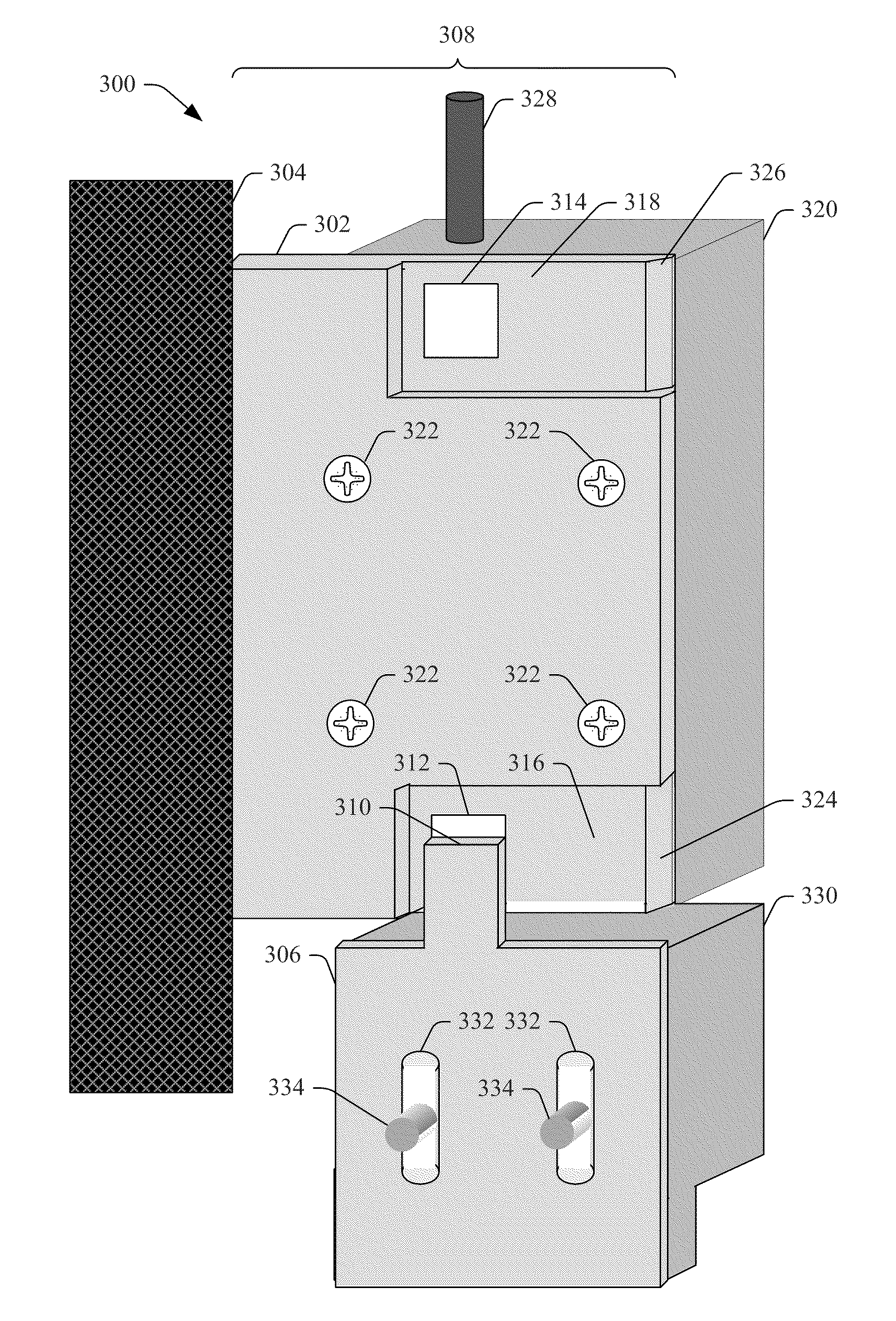
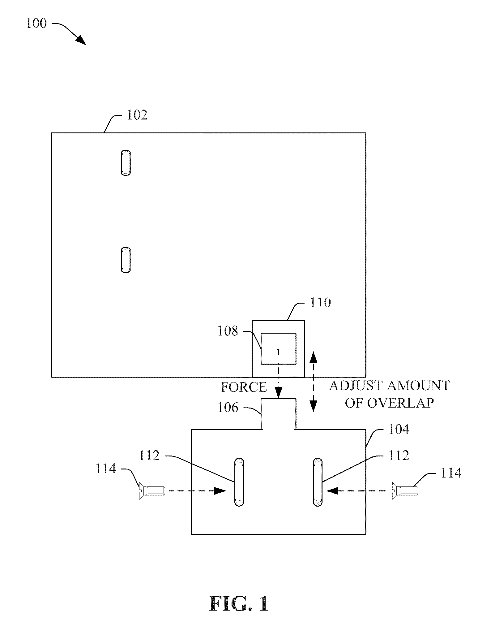
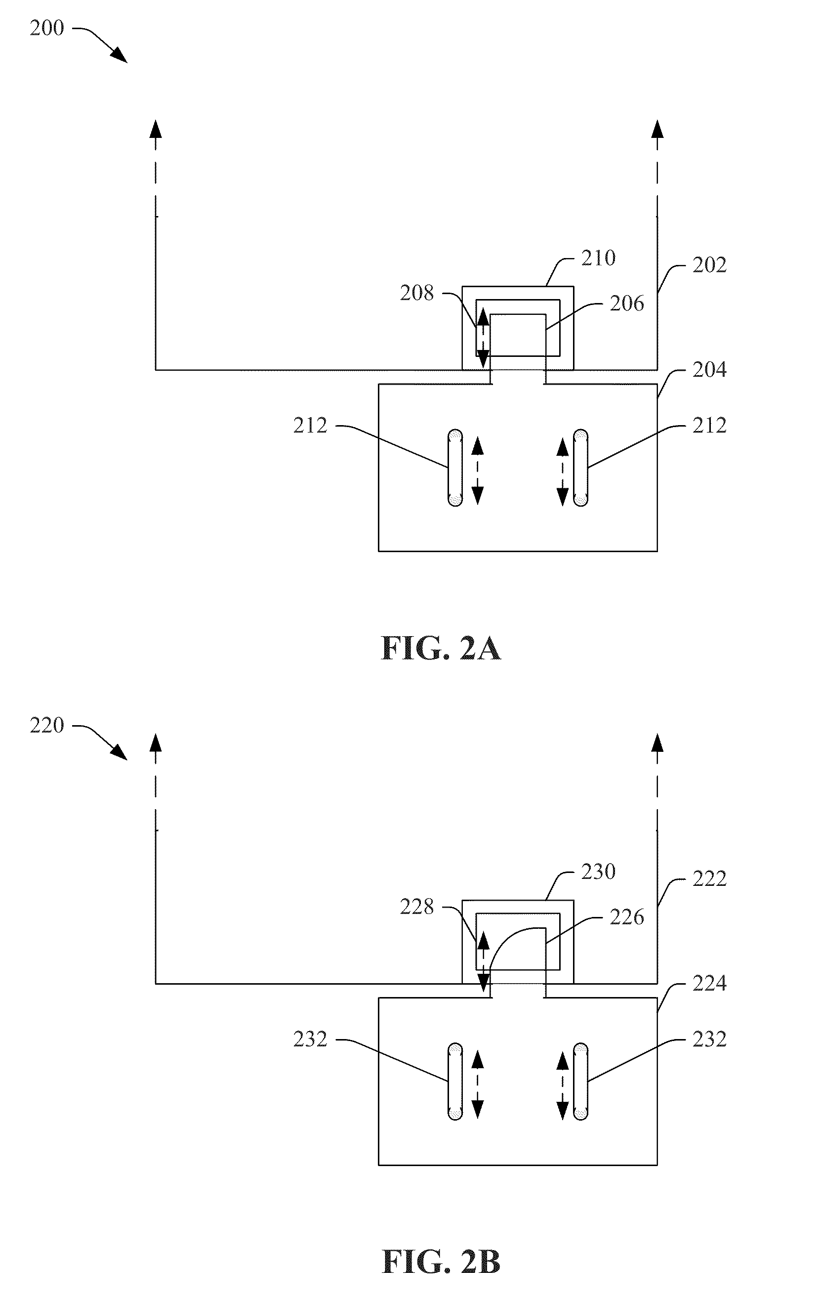
In still another aspect, the first bracket component can function as a shock or force absorber for an operation device attached to the first bracket component. For instance, the first bracket component, with the overhanging portion that overhangs beyond the door frame, can function as a type of cantilever, wherein the material that forms the first bracket component can have at least some level of elasticity, and when the door impacts and is stopped by the overhanging portion of the first bracket component, the first bracket component can absorb at least a portion of the impact of the door, which can reduce the amount of shock, vibration, or force that is impacted on (e.g., transferred to) the operation device. In an embodiment, if desired, a shock absorber component, which can be fabricated from a desired material(s) (e.g., polymer-based material, felt, etc.) and can have a desired thickness and shape (e.g., shape that corresponds to the shape of the surface of the overhanging portion with which the shock absorber component will be in contact and / or the shape of the side of the operation device with which the shock absorber component will be in contact), can be inserted between the first bracket component and the operation device to provide further shock or force absorption to thereby further reduce the amount of shock, vibration, or force impacted on the operation device when the door impacts (e.g., comes in contact with) the overhanging portion of the first bracket component when the door is being closed.
In yet another aspect, the system can comprise an operation integrity component that can sense conditions associated with the first bracket component and second bracket component, the door and associated door frame, and / or operation devices attached to the first bracket component or second bracket component to facilitate securing the door and associated defined physical area, as desired, and maintaining desirable operation of the system. In an embodiment, the operation integrity component can be associated with a sensor component (e.g., magnetic field sensor, which can be or can comprise a Reed switch or Hall-effect sensor, in accordance with various embodiments) that can be associated with (e.g., connected to, implanted in) the recessed area of the first bracket component (or, in another embodiment, in the extended portion of the second bracket component) and can sense whether recessed area (or the extended portion) is in a magnetized state or non-magnetized state and / or sense the amount of magnetic field or force applied to recessed area (or the extended portion) by the holder component, wherein, for example, the holder component can be attached to the extended portion and can apply a desired latching force to the recessed area (or another component formed thereon or attached thereto), or alternatively, can be attached to the recessed area and can apply a desired latching force to the extended portion. When the door is open, the sensor component can sense that the amount of magnetic force applied to or experienced by the recessed area (or the extended portion) is low (e.g., below a minimum threshold magnetic force level that indicates the door is properly closed) and can transmit a signal (e.g., feedback signal) that indicates the door is in an open state. When the door is closed properly, the sensor component can sense that the amount of magnetic force applied to or experienced by the recessed portion (or the extended portion) is at least the minimum threshold latching force level and can transmit a signal that indicates the door is in a closed state. The feedback signal can serve as a Magnetic Bond Sensor (MBS) output as well as a Door Status Switch (DSS) for the door latch. The sensor component can be useful, for example, when a lock component with a lock pin is attached to the first bracket component and a lock receptacle is attached to the second bracket component, as the sensor component can indicate when the second bracket component and associated lock receptacle are in the desired predefined locational position in relation to the lock pin associated with the first bracket component, so that when the lock pin is moved to the locked position, the lock pin can successfully engage the hole in the lock receptacle.

Problems solved by technology

Certain issues can arise when using such conventional door latches.
For instance, such a conventional door latch consumes energy while producing the latching.
Also, a loss of power creates a loss of latching by such door latch.
Due in part to these drawbacks, such conventional door latches may not be suitable and / or may not be allowed in certain applications, such as some safety applications, for example.
With this type of conventional door latch, it is not possible to vary the latching conditions without degrading the locking quality of the lock (e.g., safety lock).
However, such conventional door latches do not allow for adjustment of the door latch while at the same time allowing for predictable and desirable force profile settings.

Method used


Image

  • Variable adjustable door latch
  • Variable adjustable door latch
  • Variable adjustable door latch

Examples


Embodiment Construction

The disclosed subject matter is now described with reference to the drawings, wherein like reference numerals are used to refer to like elements throughout. In the following description, for purposes of explanation, numerous specific details are set forth in order to provide a thorough understanding of the disclosed subject matter. It can be evident, however, that the disclosed subject matter can be practiced without these specific details. In other instances, well-known structures and devices are shown in block diagram form in order to facilitate describing the disclosed subject matter.

As used in this application, the terms “component,”“module,”“object”, “system,” or the like can refer to hardware (e.g., lock housing, lock pin, magnet, etc.) and / or a computer-related entity, either hardware, a combination of hardware and software, software, or software in execution. For example, a component can be, but is not limited to being, a process running on a processor, a processor, an objec...


PUM

PropertyMeasurementUnit
forceaaaaaaaaaa
forceaaaaaaaaaa
forceaaaaaaaaaa

Abstract

Systems, methods, and devices that efficiently stop and latch a door are presented. A first bracket component is attached to a door frame and has an overhang portion, comprising a holder component, that extends into the doorway to act as a door stop. A second bracket component, comprising an extended portion, is desirably adjusted in position in relation to the holder component and attached to the door such that the extended portion has a desired amount of overlap on the holder component, wherein the amount of overlap corresponds to an amount of latching force in accordance with the force profile associated with the extended portion based at least in part on shape of the extended portion. An operation device is attached to the first bracket component and/or second bracket component and the door latching holds the door in the desired position to facilitate operations of the operation component.

Description

TECHNICAL FIELDThe subject specification relates generally to door latches, and in particular to variable adjustable door latches.BACKGROUNDCertain areas (e.g., rooms, secured production areas, etc.) can be accessed via a door (e.g., swinging door, sliding door, etc.), wherein, as desired, a particular defined physical area can be secured by employing a lock, a sensor, and / or other device on the door to the defined physical area. For example, an electromagnetic lock can be used to lock a door to a defined physical area, where the defined physical area can be used, for example, for storage of product, for production line operations, etc. Often, it can be desirable to be able to latch the door to hold the door in a desired position (e.g., closed position) in relation to the door frame, where, for example, the door can then be locked to facilitate securing the defined physical area.One type of conventional door latch accomplishes latching of the door by using an electromagnet with vari...

Claims


Application Information

Patent Timeline
Patent Type & Authority Applications(United States)
IPC IPC(8): G08B21/00E05C19/16B23P11/00E05B15/02
CPCE05B15/0245E05B2047/0094E05B47/02E05G1/04E05Y2201/462Y10T29/49826E05Y2201/246E05C19/16E05B2047/0068E05B2047/0067E05B17/22Y10T292/11Y10T292/17Y10T292/705
Inventor BURDENKO, MICHAEL N.
Owner ROCKWELL AUTOMATION TECH
Why Eureka
Try Eureka