In-vehicle display apparatus and display method

a technology of in-vehicle display and display method, which is applied in traffic control systems, navigation instruments, instruments, etc., can solve the problems of difficult for users, such as drivers, to know the content of an enormous amount of posted information displayed on the in-vehicle device at a glance, and the reading of posted information or the posting of information will have an adverse effect on safe driving,

Inactive Publication Date: 2011-12-01
FUJITSU GENERAL LTD
View PDF17 Cites 91 Cited by
  • Summary
  • Abstract
  • Description
  • Claims
  • Application Information

AI Technical Summary

Benefits of technology

[0012]It is an object of the present invention to at least partially solve the problems in the conventional technology.

Problems solved by technology

In addition, the in-vehicle device may perform display limit such that only a specific item is displayed.
However, in the related art, such as Japanese Patent Application Laid-open No. 2007-278807, it is difficult for the user to know the content of the posted information displayed on the in-vehicle device at a glance.
Therefore, there is a concern that the reading of the posted information or the posting of information will have an adverse effect on safe driving.
Specifically, since the in-vehicle device according to the related art displays all of the posted information, such as blog articles or tweets, acquired in real time on the screen, it is difficult for the user, such as the driver, to know the content of an enormous amount of posted information displayed on the in-vehicle device.
As a result, it is difficult for the driver to concentrate on driving, which has an adverse effect on safe driving.
In this case, it is difficult for the driver to concentrate on driving, which has an adverse effect on safe driving.
However, in this case, when driving ends, the latest information is not obtained and real-time processing deteriorates.
Therefore, it is difficult to transmit useful information in real time and effective use for example, blogs or Twitter (registered trademark).

Method used


Image

  • In-vehicle display apparatus and display method
  • In-vehicle display apparatus and display method
  • In-vehicle display apparatus and display method

Examples


Embodiment Construction

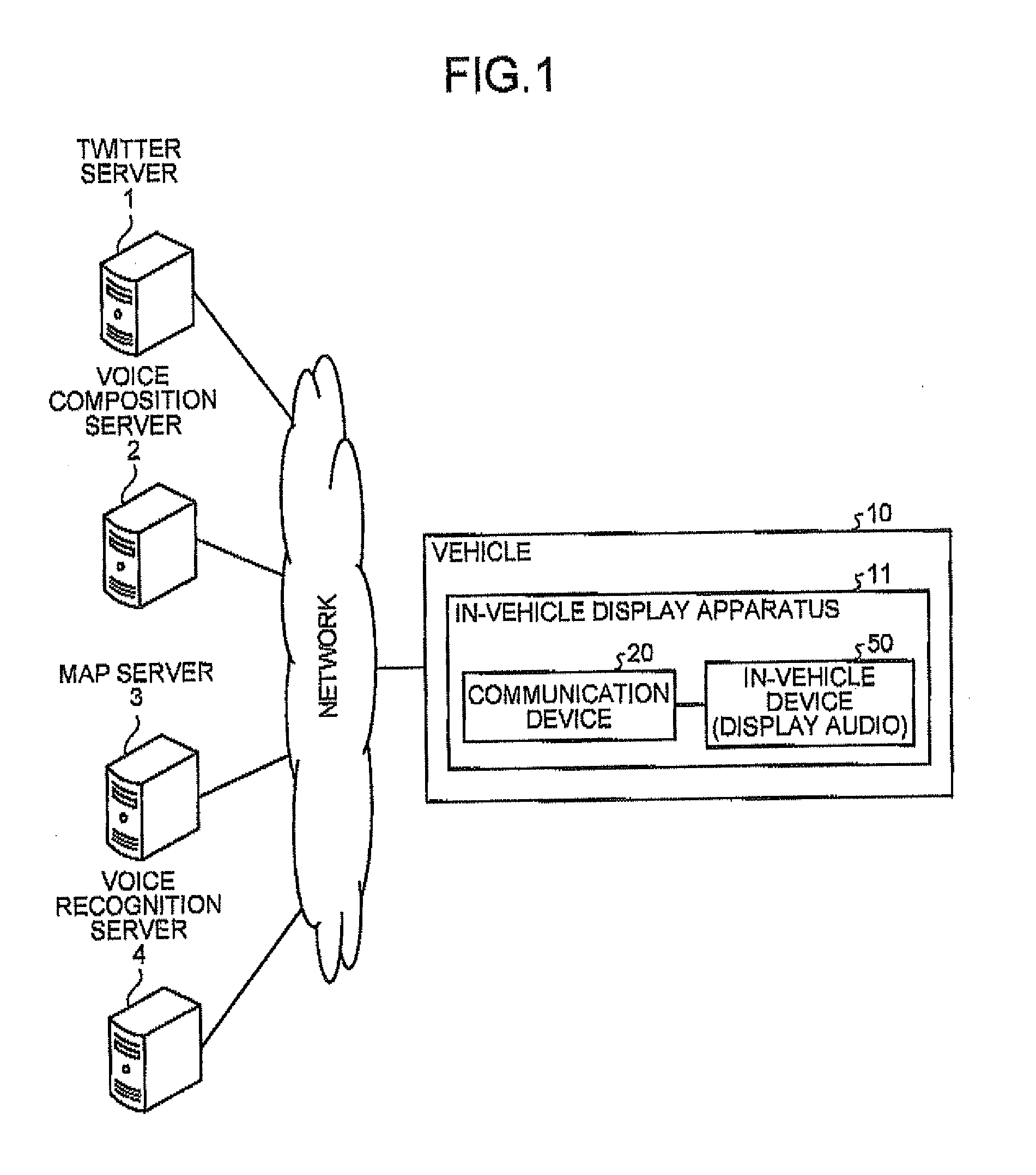
[0028]FIG. 1 is a diagram illustrating the overall structure of a system including an in-vehicle display apparatus according to a first embodiment. As illustrated in FIG. 1, the system includes a Twitter server 1, a voice composition (text-to-speech) server 2, a map server 3, a voice recognition server 4, and an in-vehicle display apparatus 11 that is provided in a vehicle 10 such as a car. In this embodiment, Twitter (registered trademark) is used as posted information, but the invention is not limited thereto. For example, post services, such as a bldg, a simple mail, and a Social Network Service (SNS), may be used as the posted information.

[0029]The Twitter server 1 is a posted information server that stores posted information, such as tweets that are posted by the individual users who are identified by their user IDs with, for example, their mobile phones. In addition, when voice data is added to the posted information, the Twitter server 1 stores the added voice data in the voi...


PUM


Abstract

An in-vehicle display apparatus includes a communication device and an in-vehicle device. The communication device acquires posted information and geographical location data indicating the destination of the posted information. Then, the communication device generates map data in which the posted information is displayed at a position specified by the geographical location data which is acquired together with the posted information. In addition, the communication device changes a method of displaying the posted information on the generated map data on the basis of the time elapsed from the posting of the information to the acquisition of the posted information and the category of the posted information. Then, the communication device transmits the map data in which the display method of the posted information is changed to the in-vehicle device. The in-vehicle device displays the received map data on, for example, a liquid crystal monitor.

Description

CROSS-REFERENCE TO RELATED APPLICATIONS[0001]This application is based upon and claims the benefit of priority of the prior Japanese Patent Application No. 2010-123593, filed on May 28, 2010, the entire contents of which are incorporated herein by reference.BACKGROUND OF THE INVENTION[0002]1. Field of the Invention[0003]The present invention relates to an in-vehicle display apparatus and a display method.[0004]2. Description of the Related Art[0005]In-vehicle devices, such as car navigation devices, have been proposed which display information that is obtained in real time by, for example, a Vehicle Information and Communication System (VICS) or a Radio Data System (RDS) using radio waves on a display. In addition, in-vehicle devices have been proposed which display real-time information that is acquired from the screen of the Internet by wireless communication using, for example, Bluetooth (registered trademark) or real-time information acquired by a distribution-type probe on a di...

Claims


Application Information

Patent Timeline
Patent Type & Authority Applications(United States)
IPC IPC(8): G08G1/0967G06F3/048G06F3/0481
CPCG01C21/3694G01C21/3697G08G1/0962G08G1/096791G08G1/09675G08G1/096775G08G1/096716
Inventor OZAKI, YUKISUKEYAMASHITA, TAKAYOSHI
Owner FUJITSU GENERAL LTD
Why Eureka
Try Eureka