Touch display apparatus and touch sensing device thereof

a touch display and touch sensing technology, applied in the field of capacitive touch sensing devices, can solve the problems of reducing the conduction efficiency of the conductive film, reducing the sensing linearity, so as to improve the sensing linearity, improve the sensing sensitivity effectively, and increase the overlap

Inactive Publication Date: 2011-12-01
AU OPTRONICS CORP
View PDF4 Cites 55 Cited by
  • Summary
  • Abstract
  • Description
  • Claims
  • Application Information

AI Technical Summary

Benefits of technology

[0013]In the embodiments of the present invention, since the width of the outer electrode strip is smaller than that of the inner electrode strip, the interval between adjacent capacitive sensing units in the first direction is decreased and the sensing signals sensed by adjacent capacitive sensing units have a rather large overlap. This can improve the sensing sensitivity effectively and can improve the sensing linearity in the first direction of the touch display apparatus and the touch sensing device.

Problems solved by technology

As to the resistive sensing technology, it is understood that from screen touch to touch point sensing, data operation and position confirmation all have limitations in physical condition.
For example, users always touch the same places in the sensing area of the touch control electronic apparatus adopting the resistive sensing technology, and therefore some specific places in the sensing area will be worn quickly to reduce the conduction efficiency of the conductive film.
Furthermore, the touch control electronic apparatus adopting the resistive sensing technology can not achieve the proximal induction (e.g., sensing the position of a finger approaching the sensing area in the situation of non-touch) and is difficult to satisfy the requirements of multi-touch sensing.
The hand shadow effect, the wear and the reduction of the touch sensitivity (e.g., resulted from the fatigue) rarely occur to the touch panel adopting the projected capacitive sensing technology.
However, in order to enhance the intensity of the capacitive sensing signal and prevent the capacitive sensing signal from being delayed or disabled, the electrode design of the conventional projected capacitive sensing technology still leaves much space to be improved.
Therefore, it is still a big problem in the touch sensing field to improve the sensing precision of the touch sensing device.

Method used


Image

  • Touch display apparatus and touch sensing device thereof
  • Touch display apparatus and touch sensing device thereof
  • Touch display apparatus and touch sensing device thereof

Examples


embodiment

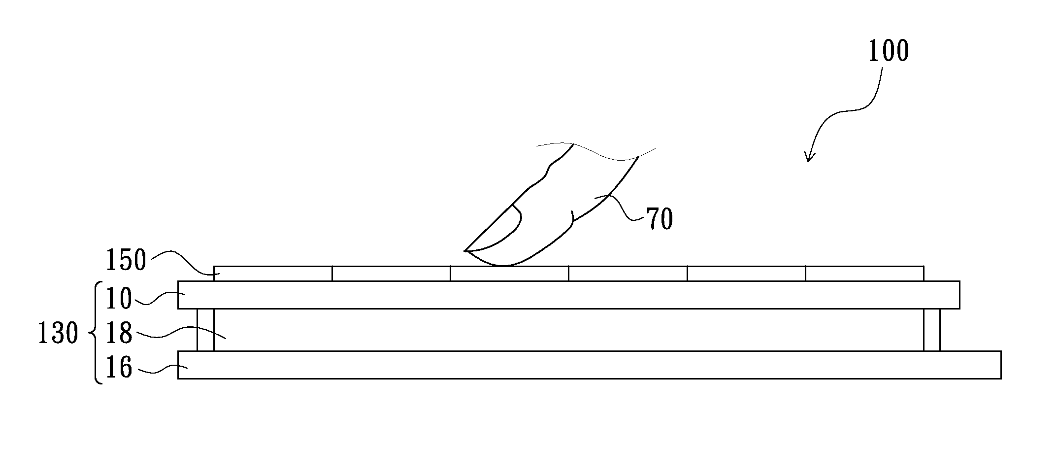
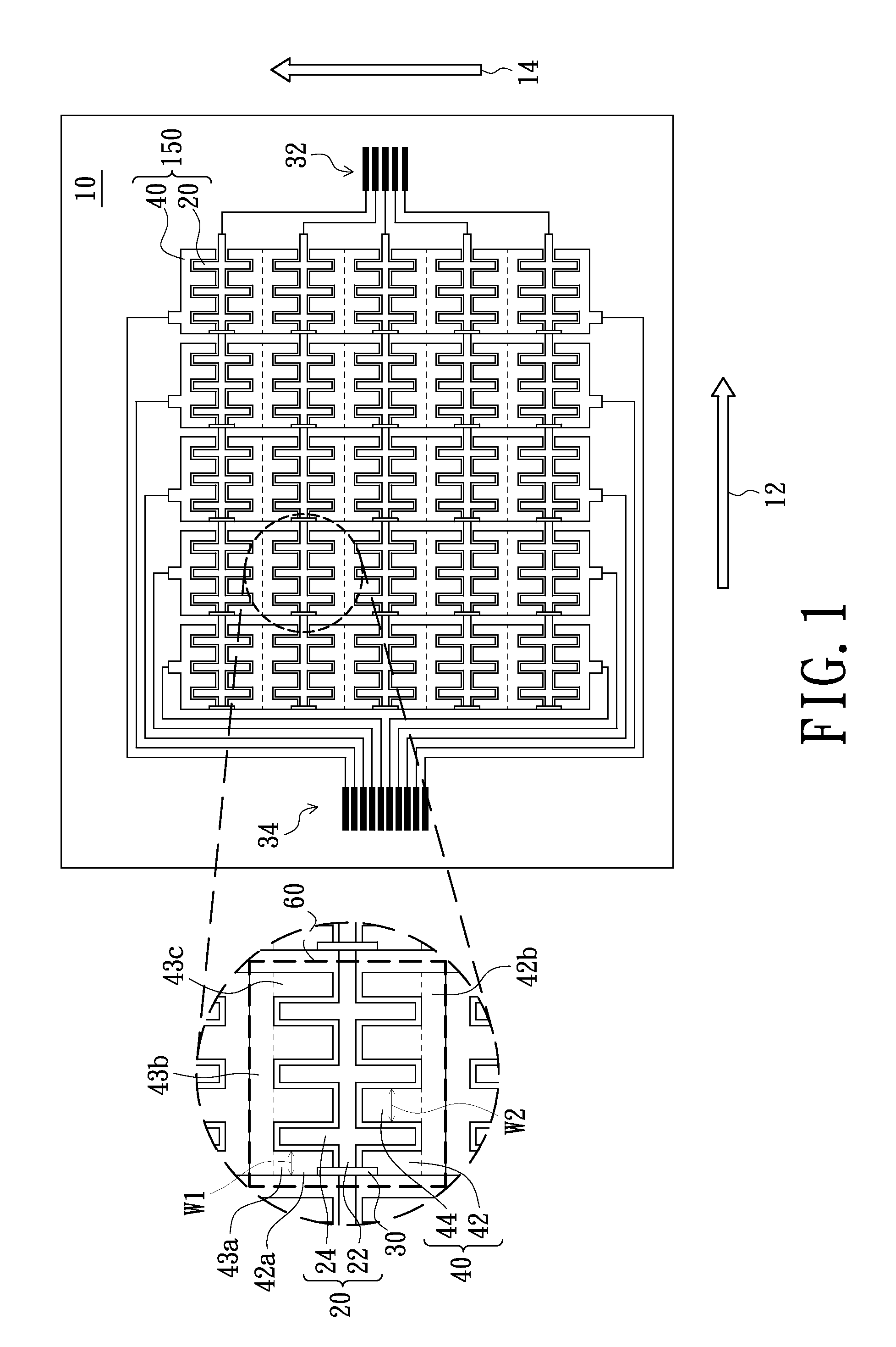
[0026]As shown in FIG. 1, the touch sensing device 150 is disposed on the substrate 10. The touch sensing device 150 comprises a plurality of sensing electrodes 20, a plurality of driving electrodes 40, a plurality of first connecting leads 32 used to connect a first circuit, a plurality of second connecting leads 34 used to connect a second circuit and a plurality of bridging lines 30. The touch sensing device 150 can be a capacitive touch sensing device. In addition, the said capacitive touch sensing device can adopt a projected capacitive touch control matrix and, more particularly, a mutual type projected capacitive touch control matrix. The sensing electrodes 20 and the driving electrodes 40 are two different electrode groups, and the sensing electrodes 20 and the driving electrodes 40 are coupled to the first connecting leads 32 and the second connecting leads 34 respectively. Wherein, each sensing electrode 20 is disposed on the substrate 10 and can be substantially arranged ...


PUM


Abstract

A touch display apparatus including a display panel and a touch sensing device disposed on the display panel is provided. The touch sensing device includes a plurality of sensing electrodes arranged in parallel to a first direction and a plurality of driving electrodes arranged in parallel to a second direction. The driving electrodes are interlaced with the sensing electrodes to form a plurality of capacitive sensing units. Each sensing electrode comprises a main electrode strip and a plurality of branch electrodes connected to the main electrode strip. The driving electrode of each capacitive sensing unit includes at least an outer electrode strip with a first width and at least an inner electrode strip with a second width in the first direction, and the outer electrode strip and the inner electrode strip interlaced with the branch electrodes, and the first width is smaller than the second width.

Description

CROSS-REFERENCE TO RELATED APPLICATIONS[0001]This application claims the priority benefit of Taiwan application serial no. 098142978, filed on Dec. 15, 2009.BACKGROUND[0002]1. Field of the Invention[0003]The present invention relates to a touch sensing device and, more particularly, to a capacitive touch sensing device.[0004]2. Description of Prior Art[0005]Generally speaking, the main touch sensing technologies adopted in current electronic apparatuses comprises resistive sensing technology, surface capacitive sensing technology, projected capacitive sensing technology, surface acoustic wave sensing technology, optics imaging sensing technology, infrared sensing technology, bending wave sensing technology, active digitizer sensing technology, etc. Since the resistive sensing technology, the surface capacitive sensing technology and the projected capacitive sensing technology have the advantages of small package volume and relative high precision, the three touch sensing technologie...

Claims


Application Information

Patent Timeline
Patent Type & Authority Applications(United States)
IPC IPC(8): G06F3/041
CPCG06F2203/04111G06F3/044G06F3/0412G06F3/0443G06F3/0446G06F3/0448
Inventor HSIEH, MING-LUNLIU, PO-YUAN
Owner AU OPTRONICS CORP
Why Eureka
Try Eureka