Stator-rotor device for an electrical machine

a technology of rotating gears and electrical machines, which is applied in the direction of dynamo-electric components, dynamo-electric circuit shapes/forms/construction, dynamo-electric machines, etc., can solve the problem of requiring the use of relatively expensive magnets, and achieve the effect of compact construction and inexpensive production

Inactive Publication Date: 2018-12-25
XYLEM IP HLDG
View PDF4 Cites 1 Cited by
  • Summary
  • Abstract
  • Description
  • Claims
  • Application Information

AI Technical Summary

Benefits of technology

[0007]The object of the present invention is to provide a generic stator-rotor device, in which preferably a compact construction can be achieved combined with an inexpensive production.
[0009]In the stator-rotor device according to the invention the pole shoes and the magnets engage with one another. For example, the pole shoes engage in the magnets. The magnets can also engage in the pole shoes. The engaging component, for example a pole shoe, has sides facing away from one another. The in each case other component, for example the magnet, comprises in each case a section opposite the sides of the first component, for example the pole shoe. The magnetic flux between the pole shoe and the magnets is thereby directed over the two sides of the engaging component and the sections of the respective other component. This enables a larger overlap between the fields of the pole shoes and the magnets to be achieved, wherein the magnetic flux can conveniently also be directed in the engagement direction. The second surface of the pole shoe on the side facing towards the magnet is larger than the first surface, by which the pole shoe is connected to the pole core and through which passes the magnetic flux that is generated by the flow of current through the windings or induces a voltage in the latter. The configuration of the stator-rotor device according to the invention allows in particular the use of inexpensive materials for producing and shaping the magnets, so that these can be manufactured easily and can be provided for an engagement by the pole shoes. For example, the magnets can be produced by an injection moulding method, which will also be discussed hereinafter. A high flux density through the first surface can be achieved even when using inexpensive magnets and with a relatively low magnet flux density in the air gap. The pole cores can thereby preferably be operated up to or close to the region of saturation magnetisation. At the same time a compact construction of the device can be achieved.
[0011]The arrangement of two sections on the sides of the engaging component facing away from one another also enables a symmetrical magnetic flux to be achieved transverse to the engagement direction and to compensate forces transverse to the engagement direction. In this way a guidance and improved bearing of the rotor and a more uniform running can be ensured.
[0013]It is advantageous if the respective engaging components—pole shoe or magnets—comprises engagement sections engaging in the respective other component—magnet or pole shoe, wherein in each case a section of the other components—magnet or pole shoe—is arranged opposite each engagement section transverse to the engagement direction on two sides facing away from one another. The engaging component, for example the pole shoe, can in particular comprise transverse to the engagement direction a plurality of projections forming the engagement sections. The projections can engage between respective sections of the magnets. In this way the second surface on the pole shoes can be formed substantially larger than the first surface and a large overlap of the magnetic fields of the pole shoes and the magnets can be achieved.
[0024]It is convenient if the engaging component—pole shoe or magnet—engages free from indentations or undercuts in the respective other components—magnet or pole shoe. This for example facilitates the installation of the device. The pole shoe and the magnet can be moved relative to one another in the engagement direction, so that they inter-engage. A movement transverse to the engagement direction is not necessary. This also allows a compact construction and inexpensive production, since undercuts and indentations can be avoided.
[0031]Preferably the matrix is a plastic matrix. In this way it is in particular possible to produce the magnets by an injection moulding method, in which the magnetic particles are already embedded into the matrix during the injection moulding. This is particularly advantageous in order to form magnets of even complex geometry. In particular this enables the magnets to be produced in a technically simple and inexpensive manner.

Problems solved by technology

This requires the use of relatively expensive magnets.

Method used


Image

  • Stator-rotor device for an electrical machine
  • Stator-rotor device for an electrical machine
  • Stator-rotor device for an electrical machine

Examples


Embodiment Construction

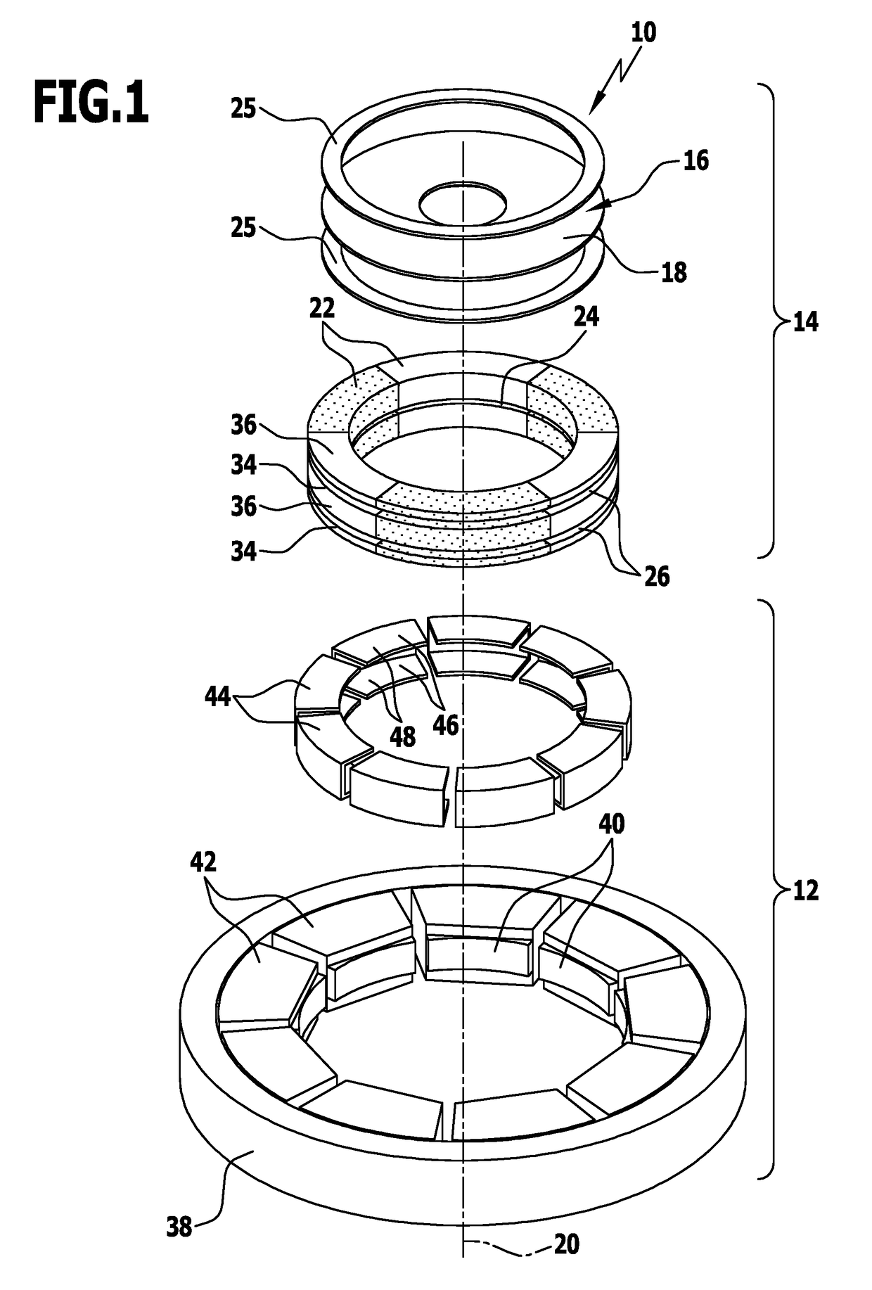
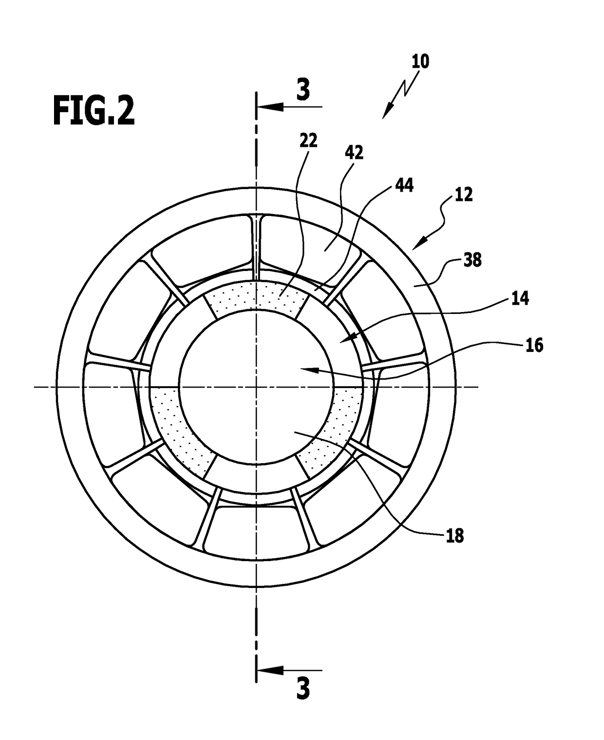
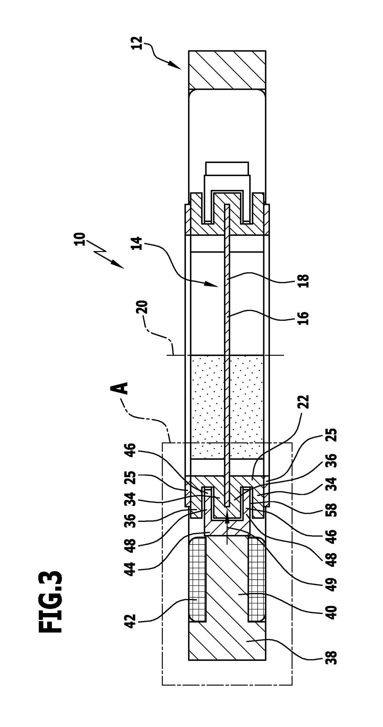
[0060]FIGS. 1 to 4 show a first advantageous embodiment of a stator-rotor device according to the invention, identified by the reference numeral 10, hereinafter termed device 10. The device 10 can be used in particular in an electric motor.

[0061]The device 10 includes a stator 12 and a rotor 14. The rotor 14 includes a carrier 16, which is here configured as a disc 18. The disc 18 defines a plane and a rotation axis 20 of the rotor 14. “Radially” and “axially” should be understood here as referring to the rotation axis 20.

[0062]In addition the rotor 14 includes a plurality of magnets 22. Six magnets 22 for example are provided here. The magnets 22 here are preferably injection-moulded magnets. The injection-moulded magnets include magnetic particles, for example ferrite magnetic particles, embedded in a matrix, for example in a plastic material. The magnets can thereby be produced in an inexpensive and technically simple manner, and in particular can be shaped. Preferably the partic...


PUM


Abstract

A stator-rotor device for an electrical machine, in particular an electric motor, includes a stator and a rotor, wherein the stator-rotor device pole cores provided with windings comprise pole shoes and magnets associated therewith. The pole shoes are connected via a first surface to a respective pole core and have a second surface that is facing towards the magnets. The pole shoes cooperate magnetically with the magnets and are separated from the latter by an air gap. The pole shoes and the magnets engage with one another in an engagement direction in such a way that in each case a section of the other component—magnet or pole shoes—is arranged lying opposite the respectively engaging component—pole shoe or magnet—transverse to the engagement direction on two sides facing away from one another. The second surface is larger than the first surface.

Description

CROSS-REFERENCE TO RELATED APPLICATIONS[0001]This patent application is a U.S. National Phase Patent Application of PCT Application No. PCT / EP2015 / 054784, filed Mar. 6, 2015, which claims priority to German Patent Application No. 102014103568.2, filed Mar. 14, 2014, each of which is incorporated by reference herein in its entirety.FIELD OF THE INVENTION[0002]The invention relates to a stator-rotor device for an electrical machine, in particular an electric motor, comprising a stator and a rotor, wherein the stator-rotor device comprises pole cores provided with windings, pole shoes and magnets associated therewith, wherein the pole shoes are connected via a first surface to a respective pole core and have a second surface facing towards the magnets, and wherein the pole shoes cooperate magnetically with the magnets and are separated from the latter by an air gap.BACKGROUND OF THE INVENTION[0003]Such a stator-rotor device (hereinafter also called “device” for the sake of simplicity) ...

Claims


Application Information

Patent Timeline
Patent Type & Authority Patents(United States)
IPC IPC(8): H02K1/27H02K21/12H02K1/08H02K1/02H02K21/16
CPCH02K1/08H02K1/02H02K1/27H02K1/278H02K21/12H02K21/16H02K1/2793H02K2201/12H02K2201/03H02K1/2796H02K2213/12H02K1/148
Inventor LAING, KARSTEN
Owner XYLEM IP HLDG
Why Eureka
Try Eureka