Liquid crystal display device

a liquid crystal display and display device technology, applied in the field of liquid crystal display devices, can solve problems such as image quality degradation, and achieve the effect of reducing brightness

Active Publication Date: 2011-12-01
MAXELL HLDG LTD
View PDF24 Cites 64 Cited by
  • Summary
  • Abstract
  • Description
  • Claims
  • Application Information

AI Technical Summary

Benefits of technology

[0013]Preferably, the light control value correcting sections include at least two selected from the following: a spatial filter which corrects the light control values so that spatial distribution of the light control values becomes more moderate in consideration of effect of leaking of light between adjoining areas; a black area control section which measures a black area based on the number of pixels whose brightness signal level is a black level threshold value or less, compares the calculated black area with a black area threshold value, and sets a minimum value of the light control value based on result of the comparison; a power control section which calculates power consumption of the backlight and corrects the light control values so that the power consumption does not exceed an electric power limit value; and a shading control section which corrects the light control values so as to relatively lower brightness in a peripheral part of a screen of the liquid crystal panel in comparison with a central part of the screen.
[0014]By the present invention, a liquid crystal display device capable of optimally setting the backlight control according to the viewing environment and the image display mode can be provided.

Problems solved by technology

However, the execution of the area control can cause deterioration in the image quality depending on the pattern, design, etc. of the screen (i.e., image displayed on the screen).

Method used


Image

  • Liquid crystal display device
  • Liquid crystal display device
  • Liquid crystal display device

Examples


Embodiment Construction

[0026]Referring now to the drawings, a description will be given in detail of a preferred embodiment in accordance with the present invention.

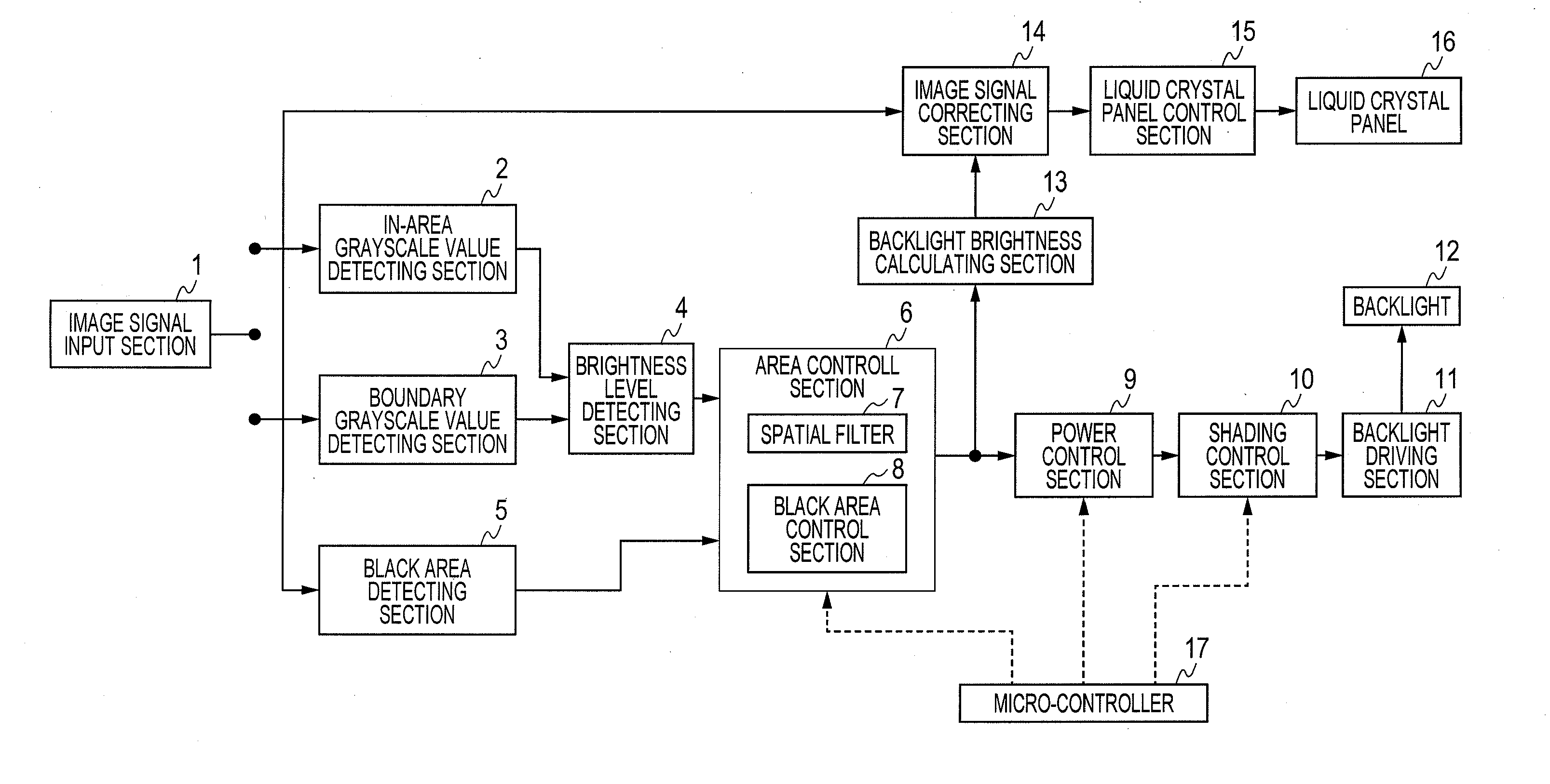
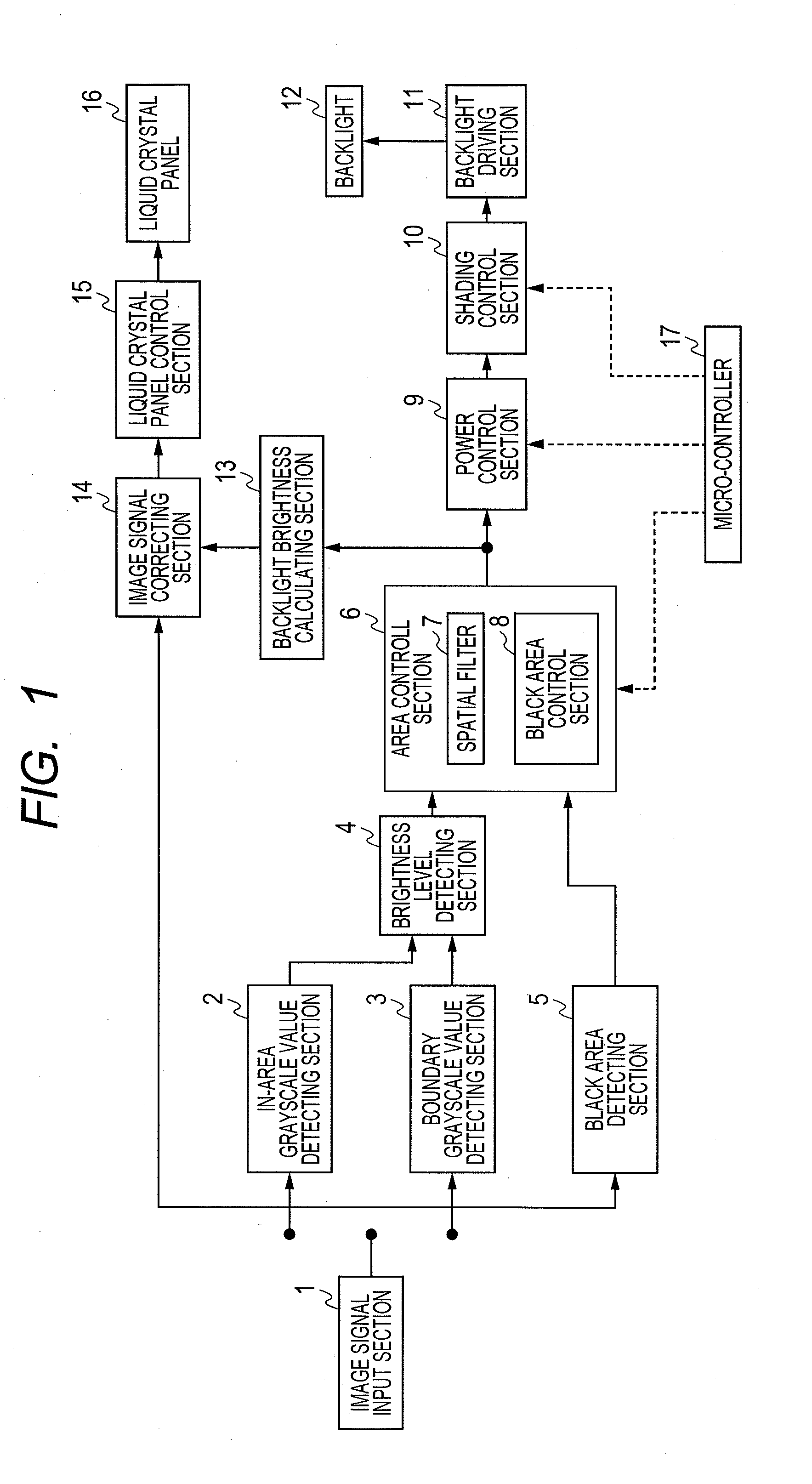
[0027]FIG. 1 is a block diagram showing a liquid crystal display device in accordance with an embodiment of the present invention. The liquid crystal display device includes an image signal input section 1, an in-area grayscale value detecting section 2, a boundary grayscale value detecting section 3, a brightness level detecting section 4 and a black area detecting section 5. Feature values of an image signal inputted to the device are detected by the detecting sections 2-5. A backlight light-control section, for generating a control signal (light control values) for a backlight 12, includes an area control section 6, a spatial filter 7, a black area control section 8, a power control section (APC (Automatic Power Control)) 9 and a shading control section 10. The backlight 12 is driven by a backlight driving section 11.

[0028]In order to gener...


PUM


Abstract

An area control section individually sets illumination intensity (light control value) of each backlight cell corresponding to each area of the display screen. A spatial filter corrects the light control values so that spatial distribution of the light control values becomes more moderate between adjoining areas. A black area control section sets the minimum value of the light control value based on a “black area” in the screen. A power control section corrects the light control values so that power consumption of the backlight does not exceed a limit value. A shading control section corrects the light control values to relatively lower brightness in the peripheral part of the screen compared to the central part of the screen. A micro-controller switches the operations of the above light control value correcting sections according to an image display mode selected by the user.

Description

CLAIM OF PRIORITY[0001]The present application claims priority from[0002]Japanese patent application serial No. JP 2010-122957, filed on May 28, 2010, the content of which is hereby incorporated by reference into this application.BACKGROUND OF THE INVENTION[0003]1. Field of the Invention[0004]The present invention relates to a liquid crystal display device which includes a backlight for illuminating a liquid crystal panel (for displaying images) from behind and executes brightness adjustment of the backlight according to an image signal inputted for the displaying of the images.[0005]2. Description of the Related Art[0006]A liquid crystal display device is equipped with a non-emitting liquid crystal panel (light-transmissive optical modulation element) and a backlight arranged behind the liquid crystal panel to illuminate the panel with light, differently from self-emission display devices (CRT, plasma display panel, etc.). In general, the liquid crystal display device displays imag...

Claims


Application Information

Patent Timeline
Patent Type & Authority Applications(United States)
IPC IPC(8): G06F3/038G09G3/36
CPCG09G3/3426G09G2320/0646G09G2360/16G09G2360/144G09G2330/021
Inventor KUBOTA, HIDENAOTSURU, YASUTAKA
Owner MAXELL HLDG LTD
Why Eureka
Try Eureka