Solar pucklight with bracket mount

a solar energy and puck light technology, applied in the field of self-contained solar energy puck light assembly, can solve the problems of reducing the usefulness of the device, and achieve the effect of directing the generated light more accurately and being convenient to position

Inactive Publication Date: 2011-12-01
INT DEVMENT
View PDF1 Cites 22 Cited by
  • Summary
  • Abstract
  • Description
  • Claims
  • Application Information

AI Technical Summary

Benefits of technology

A unique and novel design feature of the pivoting bracket assembly of the present invention is that it permits the combined bracket light assembly to be mounted to a fixed, structural mounting surface; so that when the puck light device is properly mounted the pivoting bracket assembly, the puck light device can both recharge by means of its integral solar panel receiving ambient light, and generate and project light by means of its light assembly without having to be moved or repositio

Problems solved by technology

While prior embodiments of puck lights have proven very useful in a variety of circumst

Method used


Image

  • Solar pucklight with bracket mount
  • Solar pucklight with bracket mount
  • Solar pucklight with bracket mount

Examples


case 6

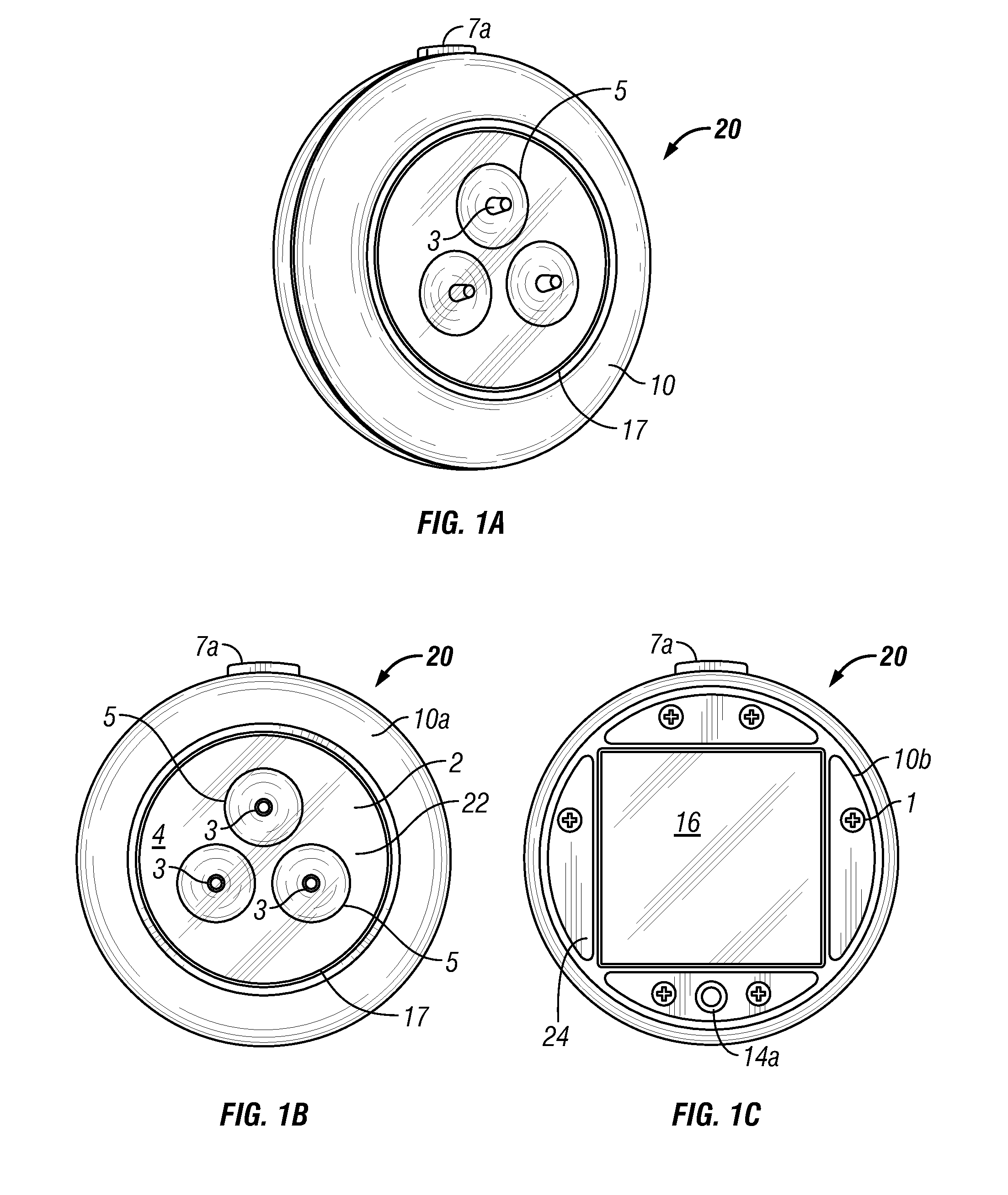
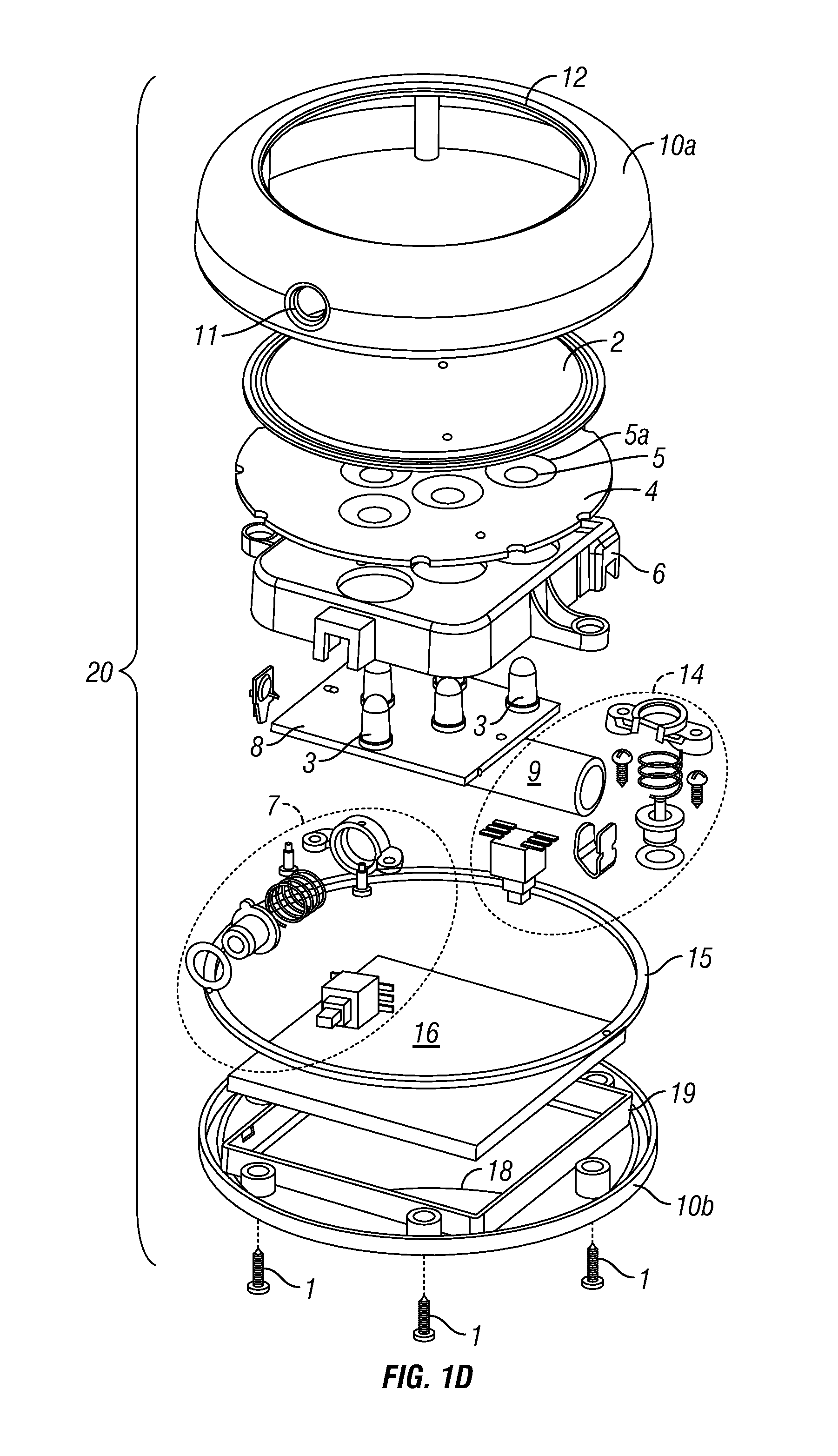
A battery case 6 may also be configured between the reflector plate 4 and the circuit board 8 to retain, protect and align the electrical storage device 9, printed circuit board 8 and various control switch assemblies. The battery case 6 includes holes which correspond to the configuration of the LEDs 3 extending from the circuit board 8 and through the holes 5 in the reflector plate 4.

While the shape the peripheral surface or edge 26 of the puck light device 20 depicted in the Figures is circular in shape, it is understood that the peripheral shape can, alternatively, be triangular, quadrangular, pentagonal, hexagonal, heptagonal, octagonal or any higher polygonal shape.

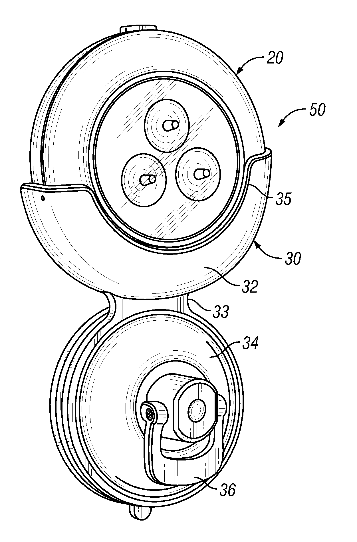
With reference now to FIGS. 2A-2B and 3A-3B, the previously described embodiment of the solar-powered puck light device 20 is shown in combination with an embodiment of the fixed bracket assembly 30 of the present invention. The fixed bracket assembly 30 includes a U-shaped receiver bracket 32 for holding the puck l...


PUM


Abstract

An improved puck light assembly comprised of a solar-powered puck light mounted in a bracket assembly, which may be securely attached to a structural mounting surface. The puck light device of the present invention is dimensioned to be a hand-held, self-contained, rechargeable, solar-powered lighting assembly. The puck light device of the present invention is mounted in a bracket assembly that allows the puck light to be both recharged and used without repositioning in the bracket assembly. In one embodiment, the bracket assembly comprises a fixed bracket assembly that includes a bracket mount for selectively attaching the bracket assembly to a smooth surface. In another embodiment, the bracket assembly comprises pivoting bracket assembly. The pivoting bracket assembly includes a receiver tray for holding the puck light device, a pivotally attached support bracket connected to a bracket mount for attaching the pivoting bracket assembly to a mounting surface.

Description

BACKGROUND OF THE INVENTION1. Technical Field of the InventionThe present invention relates to lighting devices, such as puck lights and other compact lighting devices adapted for convenient mounting and operation. More particularly, the present invention relates to a self-contained solar-powered puck light assembly having a mounting bracket, which simultaneously facilitates its use and recharging.2. Description of the Related ArtPuck lights (so named because they often resemble hockey pucks in shape) have become increasingly popular as consumer lighting devices. These devices can be used, for example, to conveniently add a light source to small areas that are insufficiently lit by overhead lighting. In one example of a common application, a puck light is mounted to the underside of kitchen cabinet to provide lighting for a countertop. Puck lights and other compact lighting devices also can be used to provide accent lighting and to provide light in areas that may have no other light...

Claims


Application Information

Patent Timeline
IPC IPC(8): F21L4/08
CPCF21L4/08F21V21/30F21V21/108F21S9/037
Inventor CHEN, CHI GON
Owner INT DEVMENT
Why Eureka
Try Eureka