Acoustically Variable Burner System

a burner system and acoustically variable technology, applied in the direction of gaseous heating fuel, stoves or ranges, lighting and heating apparatus, etc., can solve the problems of system dynamic and burner shape failure to produce realistic flame patterns

a burner system and acoustically variable technology, applied in the direction of gaseous heating fuel, stoves or ranges, lighting and heating apparatus, etc., can solve the problems of system dynamic and burner shape failure to produce realistic flame patterns

US20110294079A1Inactive Publication Date: 2011-12-01MCBRIDE DARVIL BENJAMIN +1

Image

  • Acoustically Variable Burner System
  • Acoustically Variable Burner System
  • Acoustically Variable Burner System

Examples


Embodiment Construction

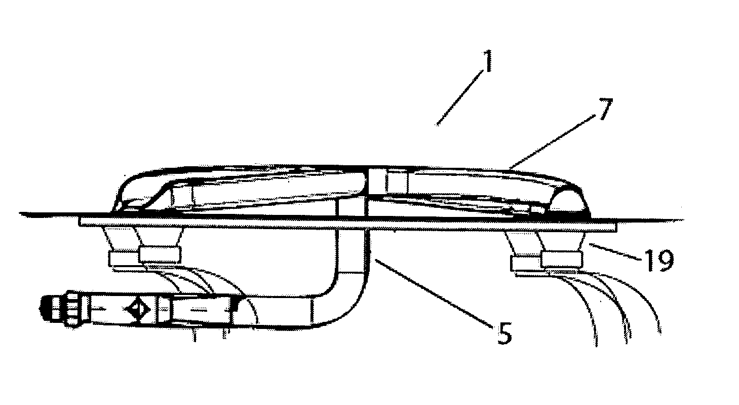
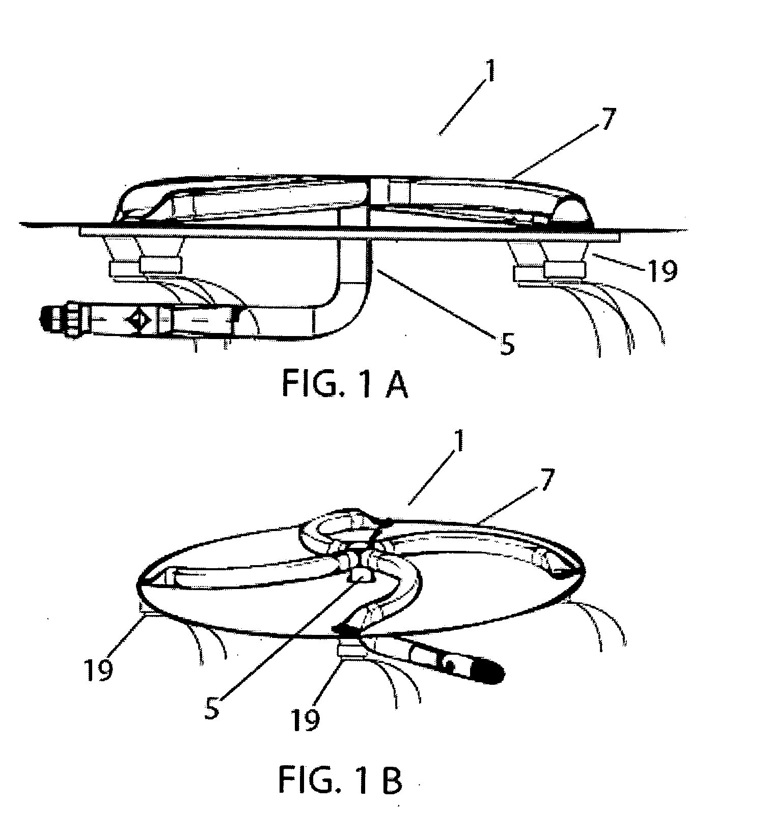
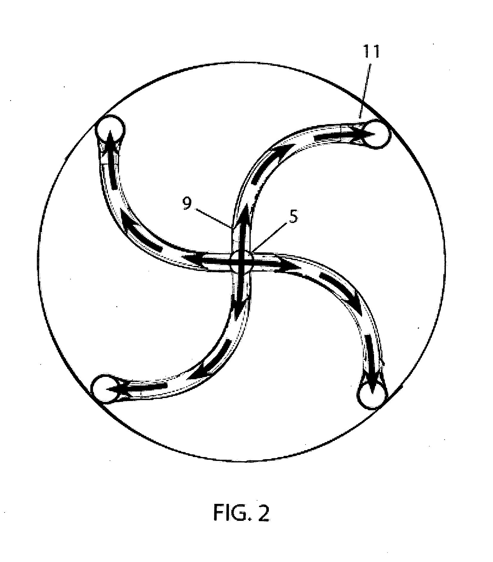
[0037]As illustrated in FIG. 1A-5, in a preferred embodiment, the present invention provides an acoustically variable burner system 1 comprised generally of a burner 3, one or more electroacoustic transducers 19 in communication with the burner 3, and a controller interface 21. As shown in FIGS. 1B and 2, the burner 3, which is configured to produce a wood burning-like flame, is comprised of a central gas chamber 5 in communication with a plurality of burner tubes 7. The burner tubes 7 are in communication with the central gas chamber 5 at a first end 9 of the burner tube 7, and a second end 11 of the burner tube 7 is disposed opposite the first end 9. The burner tubes may be linear or non-linear in shape. In a preferred embodiment, the burner 3 comprises a plurality of burner tubes 7, each burner tube having an arc-shape configuration.

[0038]The electroacoustic transducers 19 may be disposed adjacent the second ends 11 of the burner tubes 7, as illustrated in FIGS. 1A-3. Alternative...


PUM


Abstract

An acoustically variable burner system is provided, having a burner wherein the flow of gas thereto, and consequently the flame pattern resulting from the ignition of the gas, is variable by transmission of acoustic waves therethrough via an acoustically-based control system. The preferred burner design produces a realistic, wood-burning type flame pattern. An acoustic controller, such as an APPLEĀ® iPodĀ®, MP3 player, computer, etc., may be utilized to drive / control electroacoustic transducers positioned adjacent the burner, the sound waves of which are produced thereby varying the flow rate of gas to the burner gas ports, thereby varying the flame height in direct correspondence with the audio signal. Further, the flame color may be altered by introduction of flame color variant compositions exposed to the flame via a flame color variation device removably positioned adjacent the burner. The system is preferably controlled via a specialized computer program running on the acoustic controller, which enables choice of flame patterns, duration, audible audio to accompany the flame display, etc.

Description

FIELD OF THE INVENTION[0001]An acoustically variable burner system is provided, having a burner wherein the flow of gas thereto is variable by production of acoustic waves therethrough via an acoustically-based control system. Specifically, an acoustic controller, such as an APPLEĀ® iPodĀ®, may be utilized to drive transducers, the sound waves of which vary the flow rate of gas to the burner, thereby varying the flame height, etc.DESCRIPTION OF THE RELATED ART[0002]Historically, variation and control of gas flow to burners has been undertaken to control the amount of heat produced by the burner, as well as attempt to create a realistic (i.e., wood-burning) flame pattern. Conventionally, to achieve same, gas burners have comprised valve mechanisms for the control of gas flow thereto. Such valve mechanisms have varied in design tremendously, ranging from basic manual control to electromechanical control systems.[0003]In addition to mechanical and electromechanical valve systems for cont...

Claims


Application Information

Patent Timeline
01 Dec 2011
Publication
US20110294079A1
IPC
F23Q2/32; F23Q7/10
CPC
F23C99/003; F24C3/122; F23D2900/14042
Inventors
MCBRIDE, DARVIL BENJAMIN; MCBRIDE, DARVIL ANTHONE