
Control device and boat drive comprising a control device

a control device and control element technology, applied in the direction of marine propulsion, vessel construction, gearing, etc., can solve the problems of indifferent and indirect steering, play during the transmission of control movement, and unstable control elements

Active Publication Date: 2011-12-01
ZF FRIEDRICHSHAFEN AG
View PDF4 Cites 3 Cited by
  • Summary
  • Abstract
  • Description
  • Claims
  • Application Information

AI Technical Summary

Benefits of technology

The present invention aims to improve the control device of a boat drive by reducing play when operated. The invention uses a multi-stage reduction gear system with two servomotors that act in opposite directions to eliminate play in the gear system. This results in a stable steering sensation for the helmsman at the wheel. The two servomotors work together to clamp the gearwheel they are driving, ensuring a direct and stable steering movement of the boat. The invention also provides a high reduction ratio, allowing for a small torque of the electric motors to produce a large steering torque. The propulsion and steering unit passes flexibly through a hull connecting piece, allowing for vertical oscillation movements. The invention is advantageous for achieving a stable "rudder position" and ensuring a direct and stable steering movement of the boat.

Problems solved by technology

Known control devices, which comprise a servomotor or electric motor and, downstream therefrom, a toothed reduction gear system for moving a control element, often have the problem that there is play during the transmission of the control movement, particularly backlash play between the flanks of the gearwheels that mesh with one another.
As a result, in its set position, i.e. when the servomotor is static, the control element is not stable.
Control by means of such a control device has the particular disadvantage that as a result of the play the rudder or steering position concerned is unstable and the helmsman at the wheel has the sensation of indifferent and indirect steering.

Method used


Image

  • Control device and boat drive comprising a control device
  • Control device and boat drive comprising a control device
  • Control device and boat drive comprising a control device

Examples


Embodiment Construction

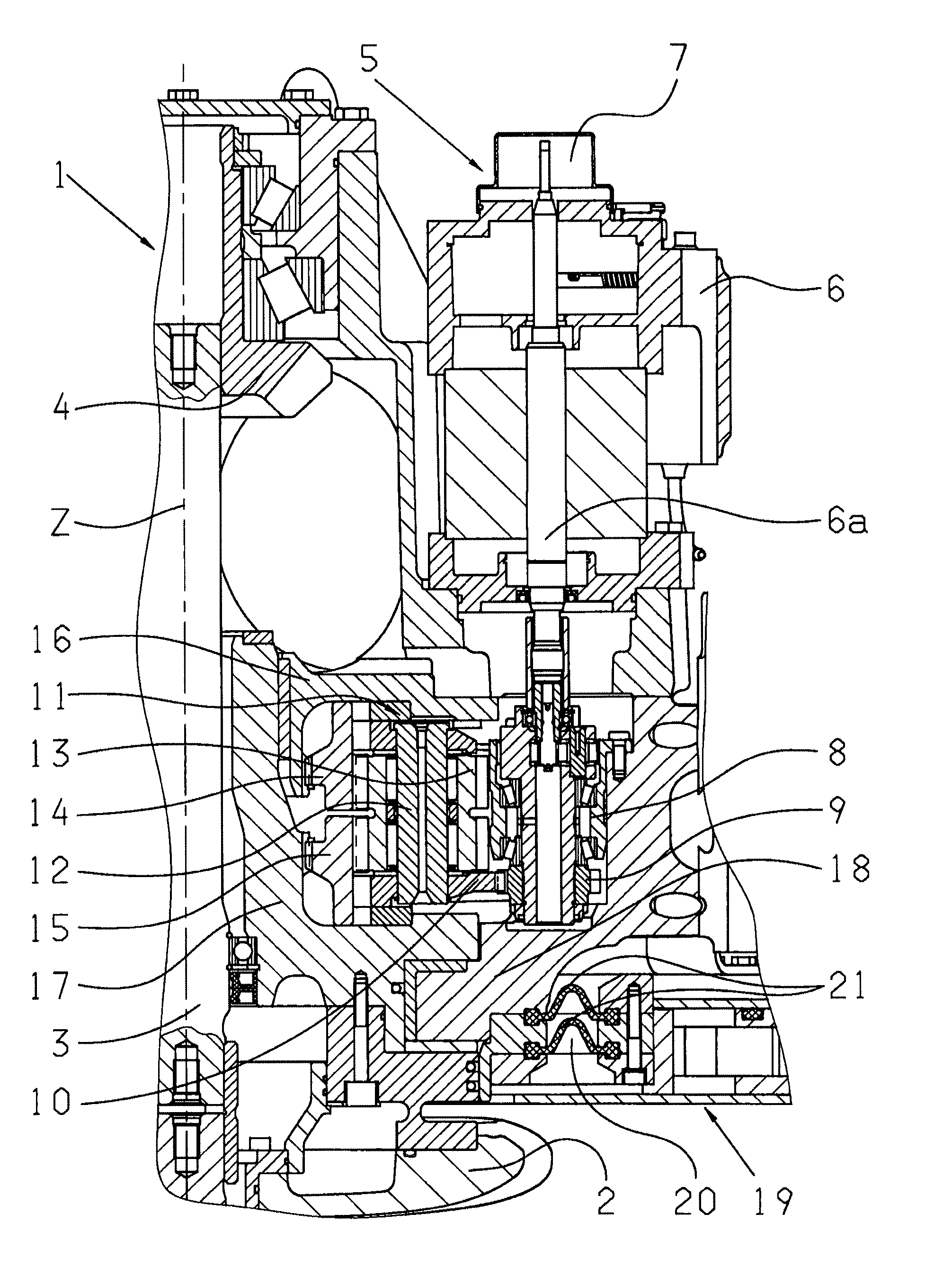
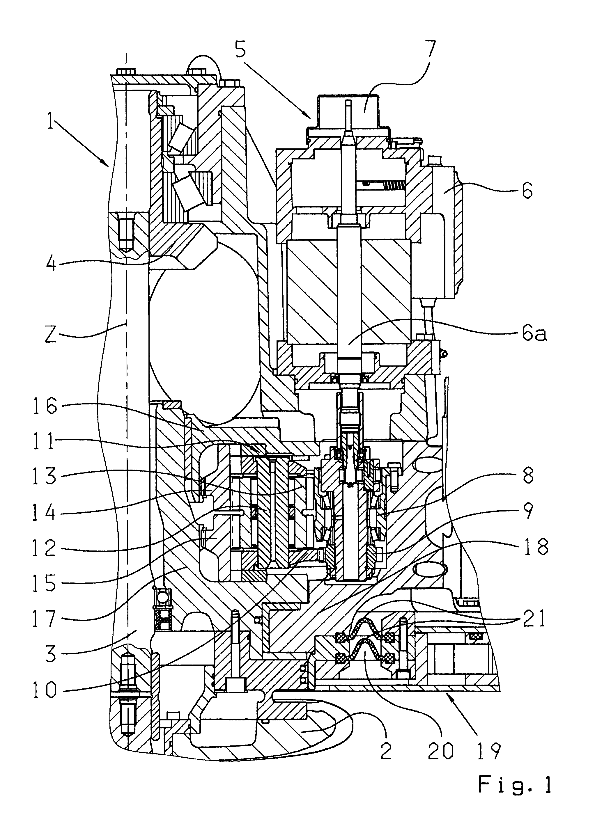
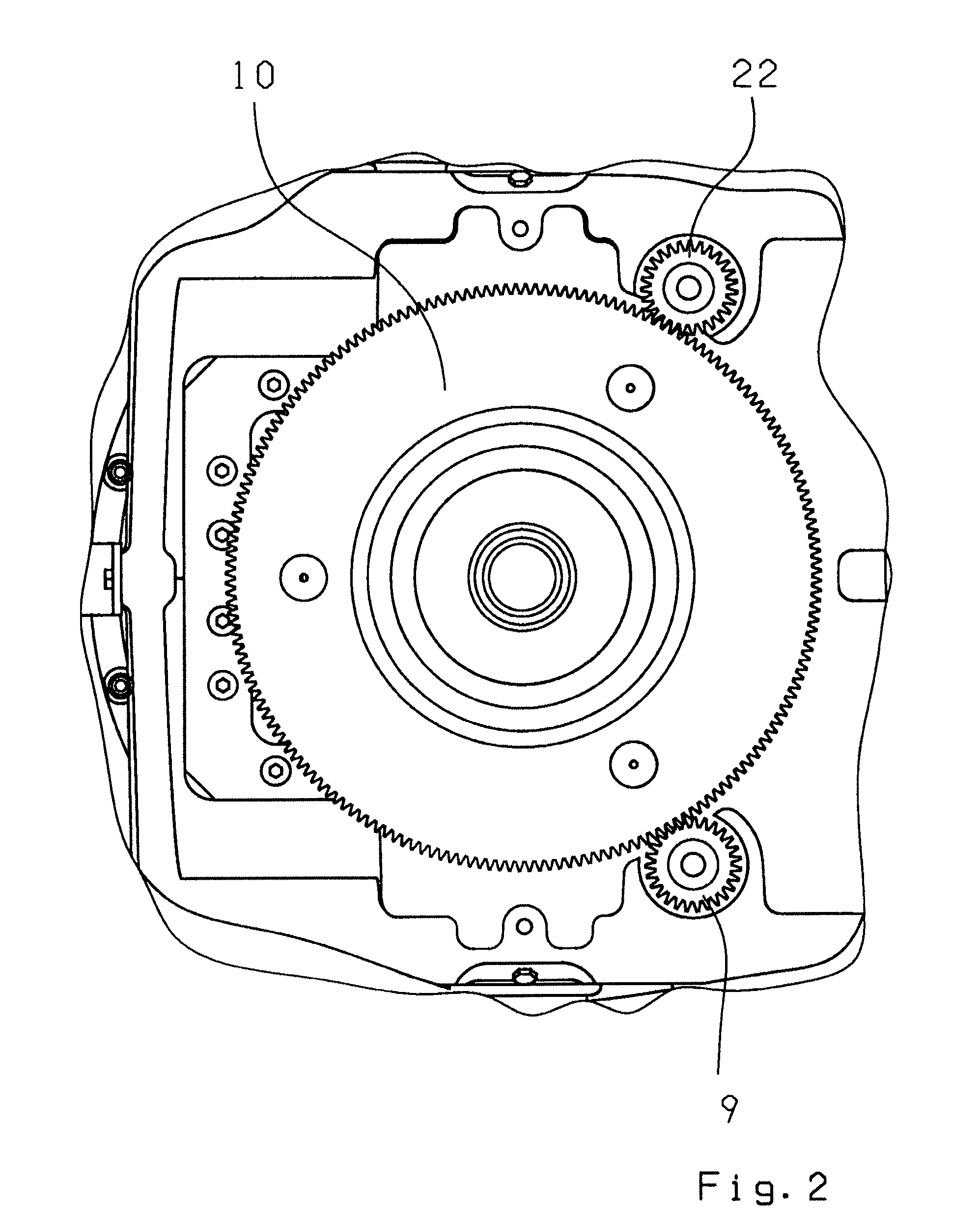
[0016]FIG. 1 shows a partial representation of a boat drive 1 with a propulsion and steering unit that can pivot about a vertical (upward) axis z, here represented in part by an underwater casing 2. The streamlined underwater casing 2 supports one propeller or two propellers (also called screws) that rotate in opposite directions (not shown), which are driven via a driveshaft 3 of an internal combustion engine (not shown) arranged in the hull of the boat. On the engine side the driveshaft 3 is driven by a bevel gear 4 (part of a bevel gear stage) and in turn it drives the propeller shaft or propeller shafts (not shown) by means of a bevel drive (not shown). The propeller shaft(s) can be swiveled by means of the pivoting underwater casing 2 so that the propulsion vector resulting from the propeller thrust forms an angle with the central axis of the vessel and therefore gives rise to a steering action. Thus, for this type of boat a conventional rudder is not needed. The underwater cas...


PUM


Abstract

A control device, in particular for a boat drive, which comprises a control drive, a reduction gear system (8, 11, 15 / 17) and a control element (2) that can be pivoted through a steering angle. The reduction gear system comprises a multi-stage toothed gear transmission (8, 11, 15 / 17) with a toothed wheel (10) on the drive input side, and the control drive comprises two servomotors (6) which drive the toothed wheel (10) simultaneously but whose driving action are slightly opposed to one another.

Description

[0001]This application is a National Stage completion of PCT / EP2010 / 051698 filed Feb. 11, 2010, which claims priority from German patent application serial no. 10 2009 000 993.0 filed Feb. 18, 2009.FIELD OF THE INVENTION[0002]The invention concerns a control device and a boat.BACKGROUND OF THE INVENTION[0003]Known control devices, which comprise a servomotor or electric motor and, downstream therefrom, a toothed reduction gear system for moving a control element, often have the problem that there is play during the transmission of the control movement, particularly backlash play between the flanks of the gearwheels that mesh with one another. As a result, in its set position, i.e. when the servomotor is static, the control element is not stable. Such control devices are also used in boat drives that comprise a propulsion and steering unit which can pivot about a vertical axis, in particular an inboard drive. Control by means of such a control device has the particular disadvantage t...

Claims


Application Information

Patent Timeline
Patent Type & Authority Applications(United States)
IPC IPC(8): B63H23/22B63H23/24F16H35/00
CPCB63H5/125Y10T74/19B63H2005/1256B63H20/12B63H25/26B63H25/34B63H25/42
Inventor GALLATO, FERNANDOBERTOLO, ADONESACCHI, DANIELE
Owner ZF FRIEDRICHSHAFEN AG
Learn More