Rework soldering jig

a soldering jig and rework technology, applied in the direction of soldering apparatus, manufacturing tools,auxillary welding devices, etc., can solve the problems of low rework efficiency, occupying too much space, and many rework soldering jigs, so as to improve rework efficiency

Inactive Publication Date: 2011-12-08
INVENTEC CORP
View PDF6 Cites 3 Cited by
  • Summary
  • Abstract
  • Description
  • Claims
  • Application Information

AI Technical Summary

Benefits of technology

[0020]The efficacy of the present invention lies in that, assembly frames of different sizes and forms can be freely assembled or dissembled on the body of the rework soldering jig, so that a shape of a combination tank formed by the body heating tank and the outer frame heating tank after the body and the assembly frame are assembled can be changed. In this way, the rework soldering jig can indeed match surface mounted slots of various forms and sizes, thereby improving the rework efficiency.

Problems solved by technology

However, in practically applications, module slots having poor or void soldering have to be removed one by one from the circuit board after strict examination, the tin paste must be recoated on the solder points, and a rework soldering step of the module slots is then performed, so as to solder the module slots on the circuit board again.
Since the conventional rework soldering jig cannot adjust the size of the heating tank, and the module slot is generally not limited to only a single size and form, if the size of the module slot does not match that of the heating tank of the rework soldering jig, peripheral electronic components are usually heated or unevenly heated resulting in damages, thus causing low rework efficiency.
However, the manufacturing of multiple sets of rework soldering jigs causes problems that the fabrication cost is too high and the numerous rework soldering jigs occupy too much space.

Method used


Image

  • Rework soldering jig
  • Rework soldering jig
  • Rework soldering jig

Examples


Embodiment Construction

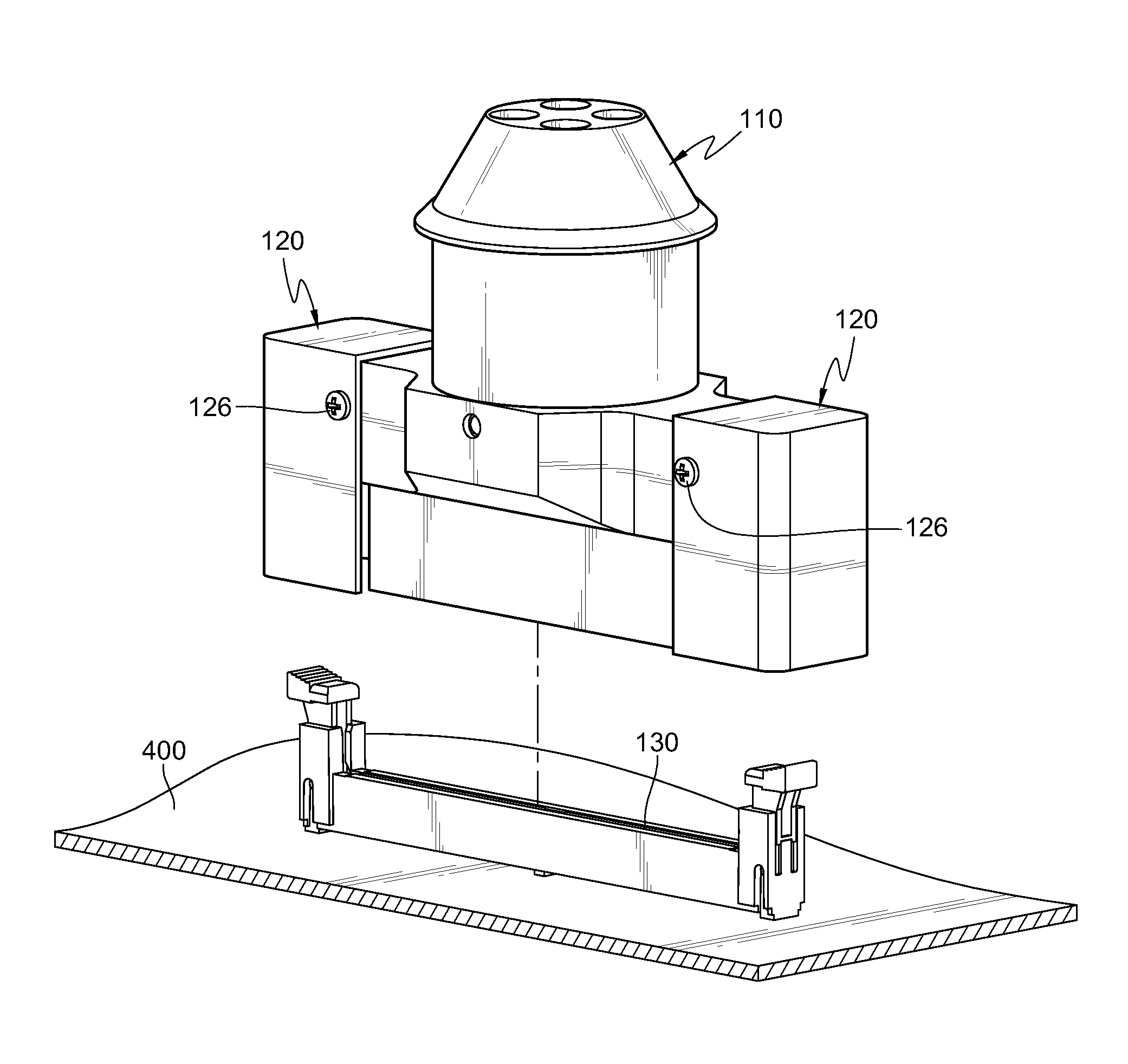
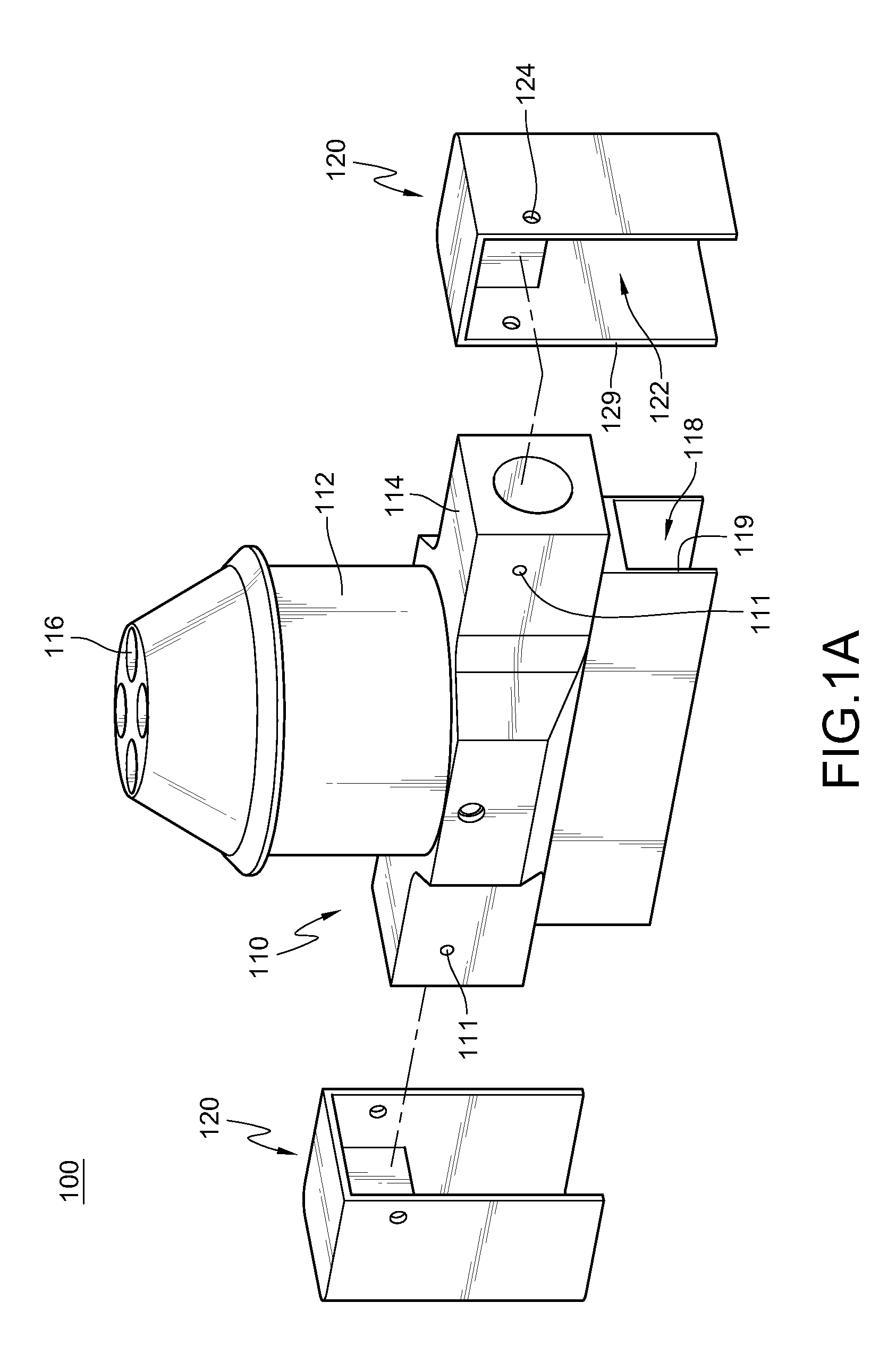
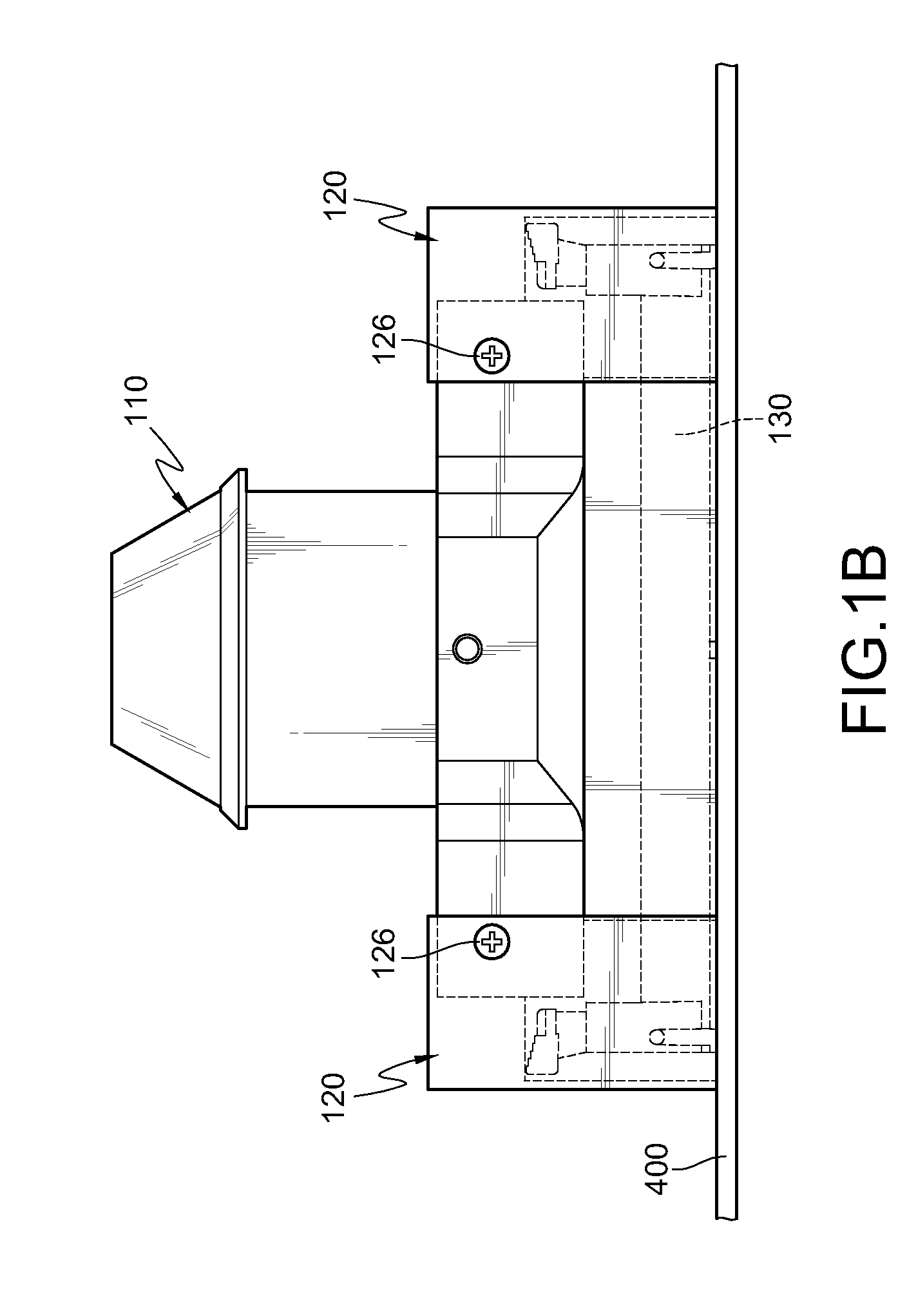
[0036]FIGS. 1A to 1C are a structural view of elements and plan and three-dimensional assembly views of a rework soldering jig 100 according to a first embodiment of the present invention. The rework soldering jig 100 functions to heat a surface mounted slot with a hot air stream so as to remove the surface mounted slot from a circuit board 400. Since various forms of surface mounted slots exist, for convenience, an example of the rework soldering jig 100 matching a first type of slot 130 is taken for illustration in this embodiment. The first type of slot 130 is an ordinary vertical surface mounted slot.

[0037]The rework soldering jig 100 comprises a body 110 and a pair of assembly frames 120. The body 110 has an air inlet pipe 112 and an air outlet plate 114. The air inlet pipe 112 has at least one air inlet 116, and the hot air stream enters through the air inlet 116. The air outlet plate 114 is connected to the air inlet pipe 112, and has a body heating tank 118. The body heating...


PUM

PropertyMeasurementUnit
sizeaaaaaaaaaa
areaaaaaaaaaaa
melting pointaaaaaaaaaa

Abstract

A rework soldering jig is used for heating a surface mounted slot. The rework soldering jig includes a body and an assembly frame. The assembly frame is detachably disposed on the body. The body and the assembly frame together wrap the surface mounted slot. Since the rework soldering jig has the detachable assembly frame, a size thereof can be adjusted according to different forms of slots.

Description

CROSS-REFERENCE TO RELATED APPLICATIONS[0001]This non-provisional application claims priority under 35 U.S.C. §119(a) on Patent Application No(s). 099117836 filed in Taiwan, R.O.C. on Jun. 2, 2010, the entire contents of which are hereby incorporated by reference.BACKGROUND OF THE INVENTION[0002]1. Field of Invention[0003]The present invention relates to a rework soldering jig, and more particularly to a rework soldering jig with an adjustable size.[0004]2. Related Art[0005]In order to solder many electronic elements on a circuit board with a limited area to enhance an integration level of a product, it is common to solder the electronic elements on the circuit board by using a surface mounting technology (SMT) instead of a conventional technology of soldering electronic elements by plating through holes (PTH).[0006]Taking a surface mounted dual in-line memory module slot (hereinafter referred to as a module slot) as an example, pins of module slots are mainly placed on solder point...

Claims


Application Information

Patent Timeline
Patent Type & Authority Applications(United States)
IPC IPC(8): H05K13/00
CPCB23K1/018B23K37/0443H05K13/0486Y10T29/53274Y10T29/53209Y10T29/5313Y10S269/903
Inventor CHEN, CHING SHUN
Owner INVENTEC CORP
Why Eureka
Try Eureka