Apparatus and process for in-mold labeling

a technology of in-mold labeling and apparatus, applied in the field of in-mold labeling, can solve the problems of high label cost, inaccuracy, and inefficiency of the foregoing representative prior art machine and process, and achieve the effect of accurate positioning of cut labels

Inactive Publication Date: 2011-12-08
CBW AUTOMATION
View PDF0 Cites 16 Cited by
  • Summary
  • Abstract
  • Description
  • Claims
  • Application Information

AI Technical Summary

Benefits of technology

[0001]This invention relates generally to in-mold labeling of plastic containers and, more particularly, to an apparatus and process that cuts non-adhesive labels from a pre-printed roll of label

Problems solved by technology

The foregoing representative prior art machines and processes variously suff

Method used


Image

  • Apparatus and process for in-mold labeling
  • Apparatus and process for in-mold labeling
  • Apparatus and process for in-mold labeling

Examples


Embodiment Construction

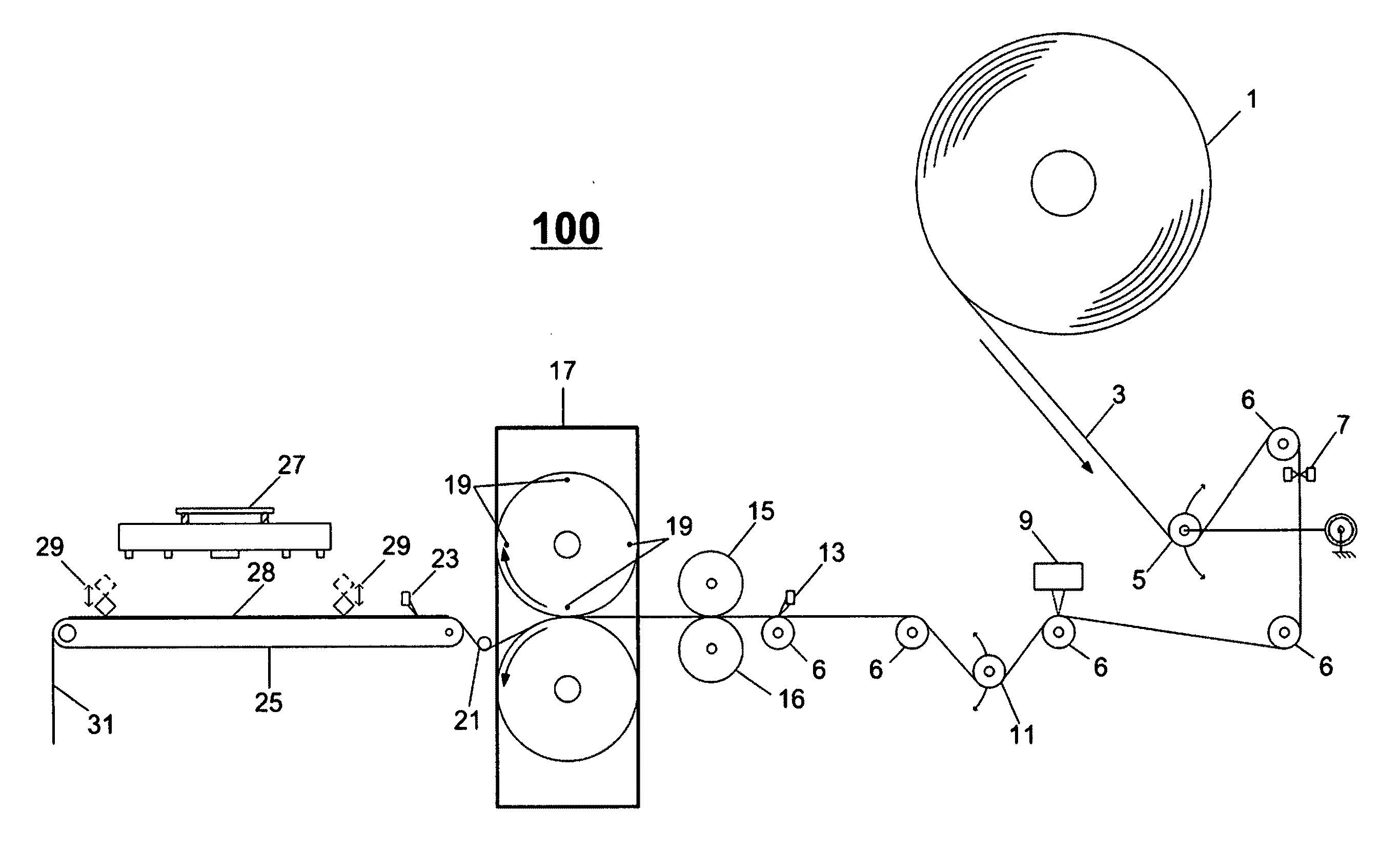
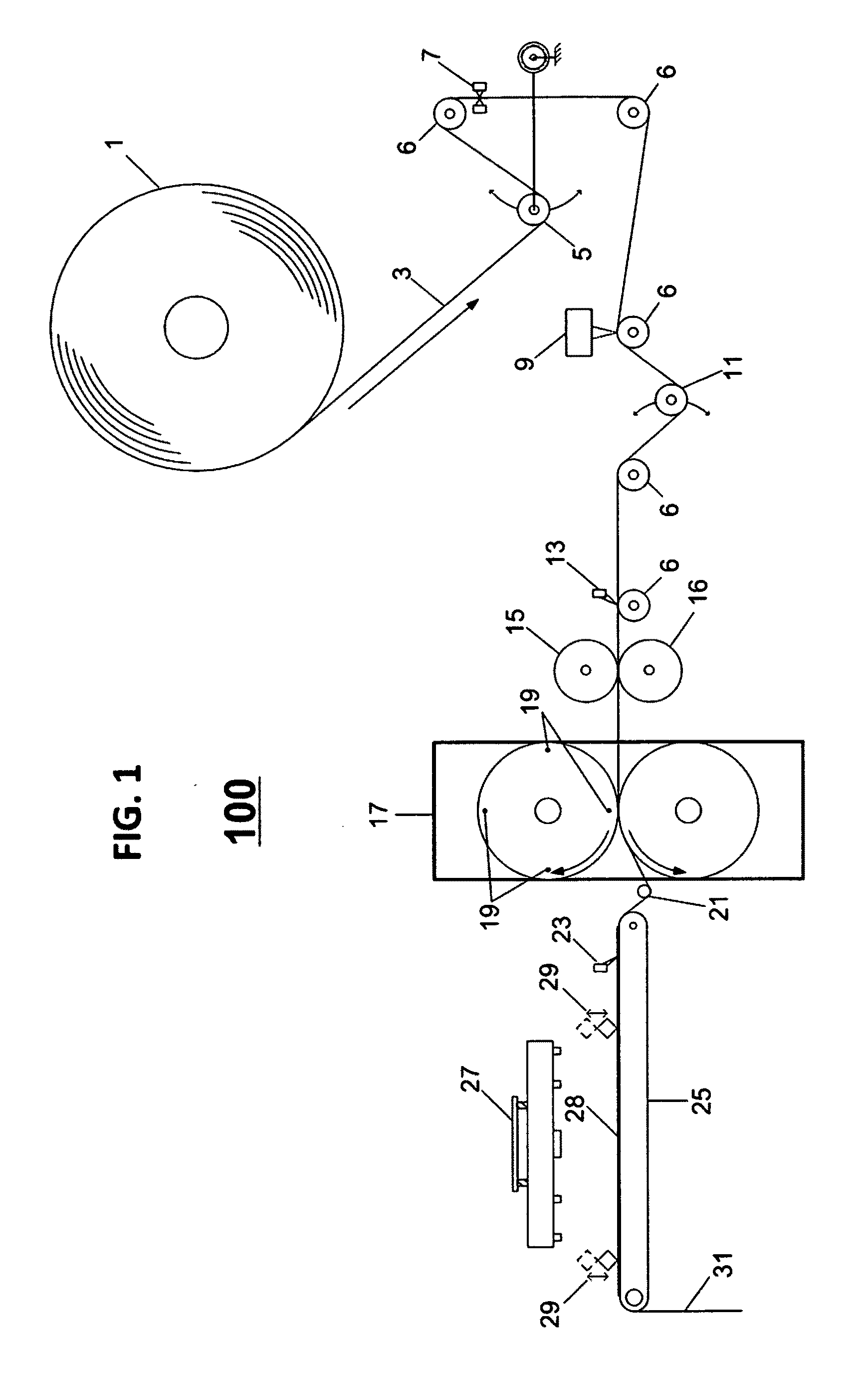
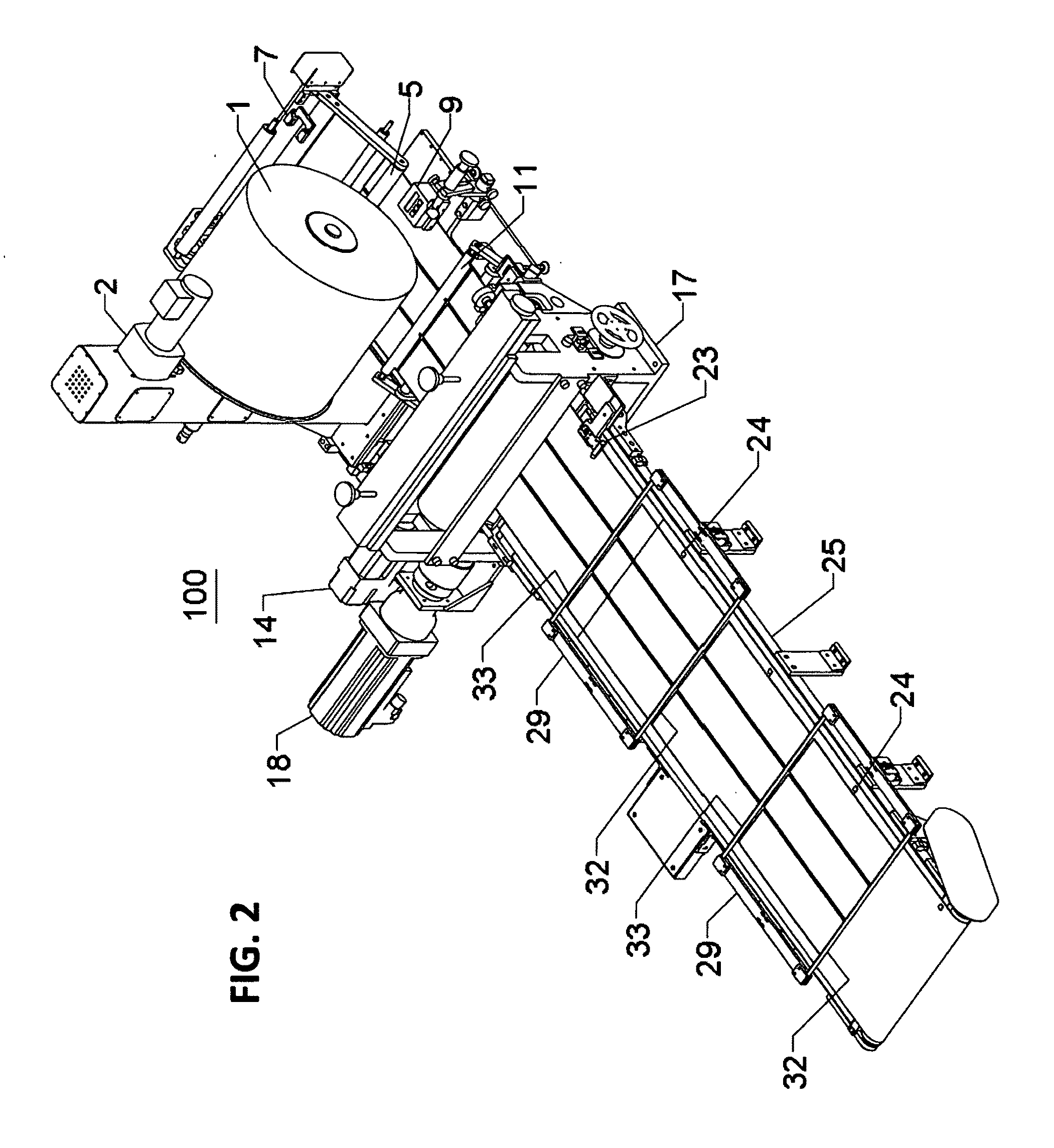
[0021]Referring now generally to FIGS. 1 and 2 and, for the details thereof, to FIGS. 3-5, there is shown an in-mold labeling apparatus 100 in accordance with the present invention that includes a label stock roll 1 containing a continuous label sheet 3 having one or more longitudinal lanes of non-adhesive labels or sets of labels 28 conventionally pre-printed thereon at predetermined intervals. A position or registration mark 24 is also pre-printed in association with each one of the labels or sets of labels 28. Label sheet 3 is unwound from stock roll 1 by means of a conventional servo motor 2, the free end being routed around a series of rolls, the first of which is an active float roll 5 that serves as the primary device for maintaining constant tension in the label sheet 3 and that also serves to provide feedback for controlling the speed of motor 2. A plurality of rolls 6 serve as idler rolls. Label sheet 3 passes an optical sensor 7 positioned adjacent one of rolls 6 that is ...


PUM

PropertyMeasurementUnit
Widthaaaaaaaaaa
Areaaaaaaaaaaa
Tensionaaaaaaaaaa

Abstract

An apparatus and process for use in an in-mold labeling application utilizes a rolled label sheet having a multiplicity of pre-printed non-adhesive labels and a pre-printed registration mark associated with each of the labels, a sensor for detecting each of the registration marks to enable alignment of the label sheet in a predetermined longitudinal position before labels are cut therefrom; a set of driven pinch rolls for moving it forward or backward; a circumferential die cutter for cutting one or more labels from the label sheet; a passive float roll following the die cutter for creating a controlled loop in the label sheet that permits the die cutter to operate independently of a vacuum conveyor that follows the float roll, the vacuum conveyor including a sensor to detect each of the registration marks for enabling alignment of the label sheet in a position of registration thereon; and a plurality of vacuum plenums along the vacuum conveyor for selectively receiving hold down vacuum from an external source for maintaining the label sheet in its position of registration during conveyance to a predetermined label removal position, the hold down vacuum then being released to permit removal, by an external pick and place device, of one or more of the previously-cut labels.

Description

BACKGROUND AND SUMMARY OF THE INVENTION[0001]This invention relates generally to in-mold labeling of plastic containers and, more particularly, to an apparatus and process that cuts non-adhesive labels from a pre-printed roll of label stock more efficiently and that then accurately positions the cut labels on a vacuum conveyor for further processing by conventional pick and place machinery employed in plastic molding processes.[0002]Various in-mold labeling techniques are known in which a label is cut from a roll of label stock and then placed within the cavity of a mold and in which the label becomes adhered to the surface of an article formed within the mold.[0003]U.S. Pat. No. 5,286,317 to Treat et al. describes a mechanism for rotary die cutting labels from a carrier web that is continuously or intermittently moving. An eye mark is provided on the web in association with each of the labels for control purposes while the web is being pulled continuously through the die cutting st...

Claims


Application Information

Patent Timeline
IPC IPC(8): B32B37/02
CPCB29C49/2408B29C51/167B29C2045/14918B29C2049/2412Y10T156/12Y10T156/1365Y10T156/1322Y10T156/1062Y10T156/1052B29C2049/2449
Inventor CARSON, DAVID E.DAVIS, MATTHEW C.SAHRLE, THOMAS A.WHITE, GEOFFREY S.WOODEN, ROBERT J.
Owner CBW AUTOMATION
Why Eureka
Try Eureka