
Retrofit Assembly for Self-Mobilization of a Transport Unit

a transportation unit and self-mobilization technology, applied in the direction of electric propulsion mounting, scaffold accessories, building scaffolds, etc., can solve the problems of complicated propulsion unit operation, heavy materials that the cart may be carrying, and difficulty in transporting the operator of the scaffold

Inactive Publication Date: 2011-12-08
HUNTLEY PAUL N +1
View PDF15 Cites 17 Cited by
  • Summary
  • Abstract
  • Description
  • Claims
  • Application Information

AI Technical Summary

Benefits of technology

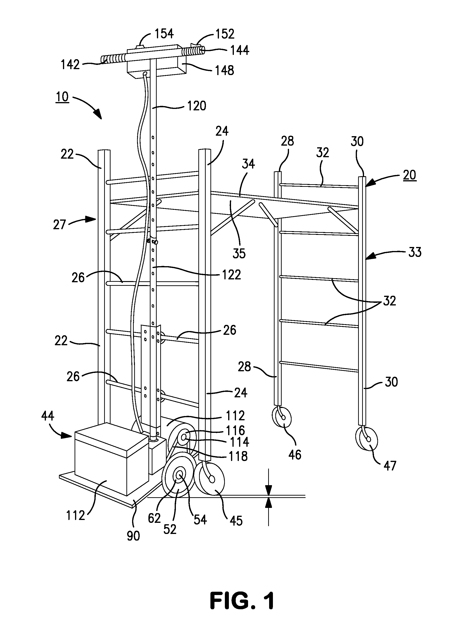
[0011]The retrofit assembly comprises a drive assembly and a steering assembly. The drive assembly includes a pair of freely rotating wheels that are spaced apart from each other and which share a common axle. The spacing of the wheels on the axle generally approximate a distance slightly less than the spacing between the transport unit's front caster wheels. It will be understood that the spacing between the wheels on the retrofit assembly can also be equal to or greater than the caster wheel spacing. If it is desired to have the wheel spacing equal to or greater than the spacing of the transport unit's front caster wheels, the front caster wheels of the scaffold can be removed in favor of using the wheels of the drive assembly. In addition, the rear caster wheels of the transport unit can be set to a locked position (as opposed to being freely rotating) to prevent a drifting or “fish-tailing” of the rear portion of the unit when it is actively mobilized by the retrofit assembly.
[0015]The base that communicates with the axle for carrying the assembly's motor and power source preferably rests upon the axle and is secured thereto by means of at least two bearing assemblies, each of which comprises a block member that includes an opening for receiving a bearing means about the circumference of the opening for receiving the axle of the drive assembly therethrough. The fixation of the bearing means within each opening allows the axle to freely rotate in the bearing assembly.

Problems solved by technology

As a result, the scaffolding can only be turned in a direction other than forward or backward by powering only one of the propulsion units while the other propulsion unit is non-powered or reverse-powered, thereby complicating the operation of the propulsion unit.
However, only one wheel is involved for the powering and directional movement of the scaffolding cart thereby making it difficult to transport the scaffold's operator as well as heavy materials that the cart may be carrying.

Method used


Image

  • Retrofit Assembly for Self-Mobilization of a Transport Unit
  • Retrofit Assembly for Self-Mobilization of a Transport Unit
  • Retrofit Assembly for Self-Mobilization of a Transport Unit

Examples


Embodiment Construction

[0034]Throughout the following description, the preferred embodiments and examples are intended as exemplars rather than limitations on the apparatus of the present disclosure.

[0035]A motorized, two-wheeled retrofit assembly is disclosed for integration with a movable transport unit in order to propel and control the movement of the unit from one location to another.

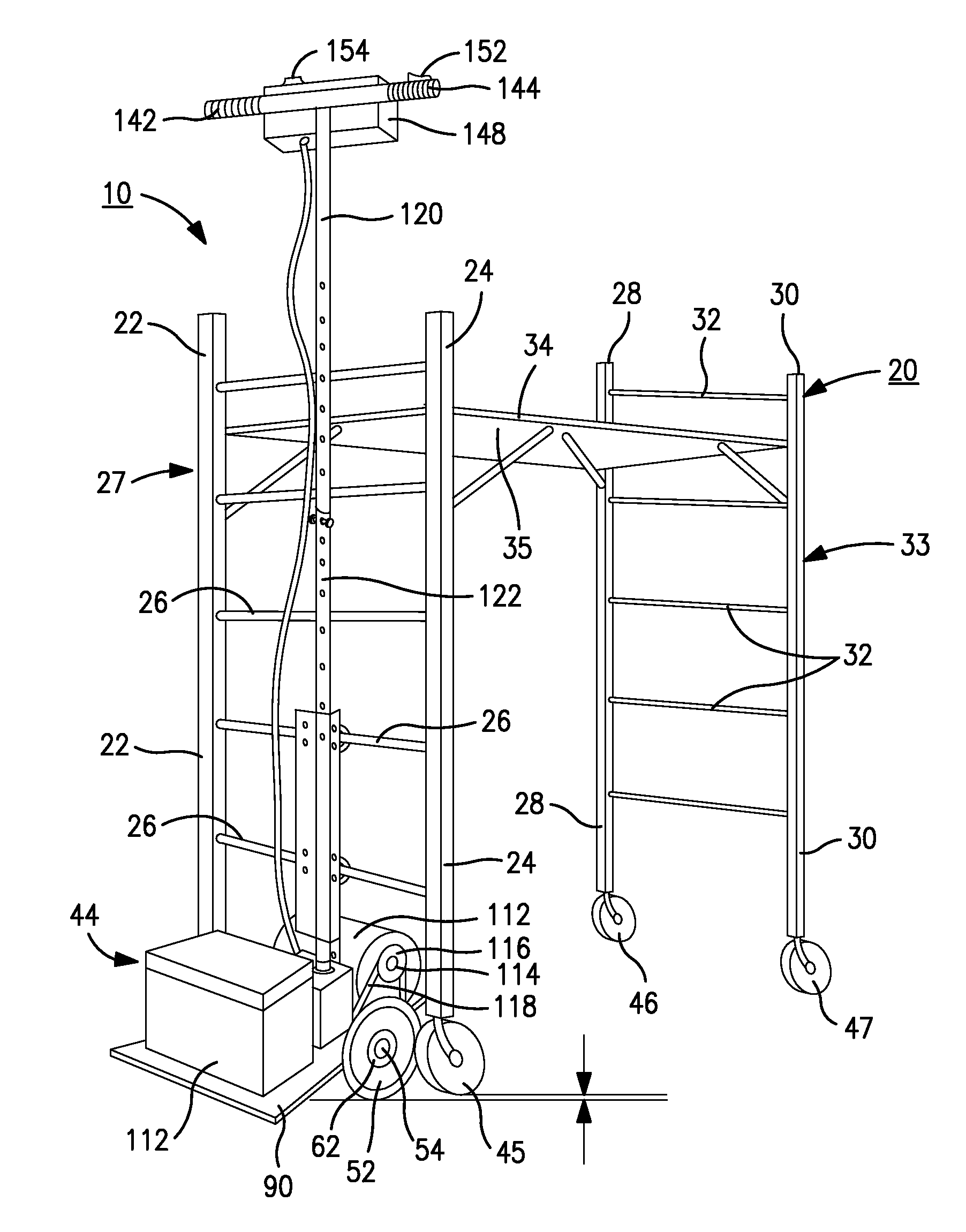
[0036]Referring to the drawings, in particular FIG. 1, there is shown for illustrative purposes only, a motorized retrofit assembly 10 incorporated with a transport unit 20 in the form of a 4-wheeled movable scaffold. In the illustration shown, the scaffold has, what is referred to in the construction industry, a “Baker” type construction wherein two vertical posts 22 and 24 are rigidly connected by laterally disposed cross members 26 to define a front framework 27. In similar fashion, vertical posts 28 and 30 are connected by laterally disposed cross members 32 defining a rear framework 33. Vertical posts 22, 24, 28, 30...


PUM


Abstract

A motorized, two-wheeled retrofit assembly converts a portable, four-wheeled transport unit, such as a scaffold, to a self-propelled, power driven unit for directional movement from one location to another. The retrofit assembly is attached to the transport unit in a manner that immobilizes or replaces the front wheels of the transport unit. The retrofit assembly comprises a drive assembly and a steering assembly. The drive assembly includes a pair of freely rotating wheels that are spaced apart from each other and share a common axle. Each freely rotating wheel is disposed adjacent to and detachably engaged with a corresponding slip drive wheel that is fixed to the axle for driving the freely rotating wheels. The drive assembly further comprises a motor; a drive mechanism that operatively interconnects the motor with one of the slip drive wheels for turning the retrofit assembly axle; a power source for the motor; and a base communicating with the axle for carrying the assembly motor and power source. The steering assembly comprises a vertically adjustable steering column.

Description

CROSS-REFERENCE TO RELATED APPLICATION[0001]This application claims the priority of U.S. Provisional Patent Application No. 61 / 342,027 filed on Apr. 8, 2010, the entirety of which is incorporated herein by reference.BACKGROUND[0002]1. Field of the Subject Matter[0003]The subject matter herein relates to movable transport units used in the construction industry. More specifically, a retrofit assembly is disclosed for converting a manually movable transport unit, such as a scaffold, to a power driven unit for its movement in selective directions from a remote driving and steering location on the scaffold. The retrofit assembly, when attached to the transport unit, can be operated from a platform on the unit that is elevated above the ground regardless of the height of the platform.[0004]2. Related Art[0005]Various devices and apparatus have been disclosed in the prior art for powering and steering scaffolds. U.S. Pat. No. 3,232,375 to Warthen discloses a scaffold containing a powering...

Claims


Application Information

Patent Timeline
IPC IPC(8): E04G5/00E04G3/28B60K1/00
CPCE04G1/20E04G1/24E04G1/28B62B5/0079B62D51/001B62B2207/02B62D53/045B62B3/002B62B3/02B62B2202/90B62D53/02E04G2001/244
Inventor HUNTLEY, PAUL N.RAUDAT, JOHN
Owner HUNTLEY PAUL N
Learn More