
Versatile microwave heating apparatus

a microwave heating and microwave technology, applied in the field of microwave heating, can solve the problems of limited effectiveness and poor crisp function, and achieve the effect of improving the uniformity and/or the total power of the crisp effect, and improving the uniformity of the crisp function

Active Publication Date: 2011-12-08
WHIRLPOOL CORP
View PDF5 Cites 23 Cited by
  • Summary
  • Abstract
  • Description
  • Claims
  • Application Information

AI Technical Summary

Benefits of technology

[0007]More specifically, present invention may provide a versatile microwave heating apparatus with an improved crisp function.
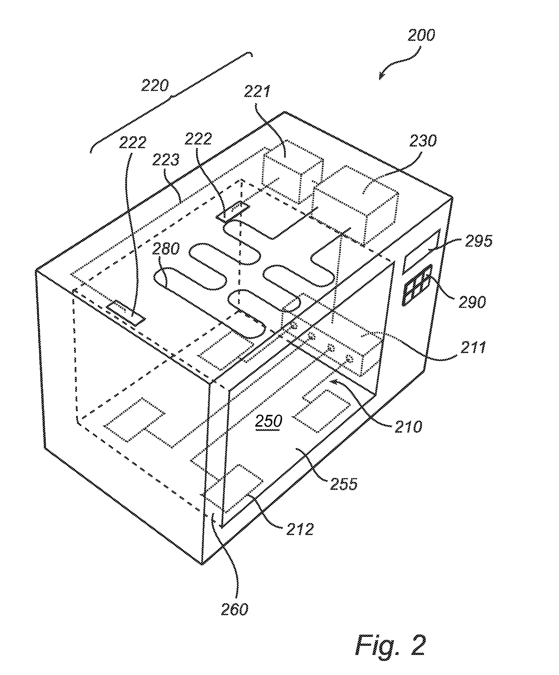
[0020]Further, solid-state microwave generators are relatively more compact than magnetrons and, thus, are advantageous in domestic applications where a plurality of microwave sources needs to be used such as for implementing the first and second microwave supply systems and for improving the uniformity of the crisp function. However, for professional applications, wherein significantly larger apparatus than home appliances are used, it may be envisaged to use a plurality of magnetrons for improving uniformity of e.g. the crisp function. In addition, the uniform distribution of a plurality of solid-state microwave generators in the lower part of the cavity is advantageous in that rotation of the browning plate (which rotation usually is used for improving uniformity) is not required, thereby providing a larger freedom for designing the browning plate, which does not have to be circular. The arrangement of the plurality of solid state microwave generators in the lower part of the cavity (e.g. at the cavity bottom) may therefore allow for a rectangular browning plate or any other shape of browning plates.

Problems solved by technology

As microwave ovens are primarily used for standard microwave heating (i.e. volume heating by excitation of cavity modes), the effectiveness of the crisp function is often limited and rather poor.

Method used


Image

  • Versatile microwave heating apparatus
  • Versatile microwave heating apparatus
  • Versatile microwave heating apparatus

Examples


Embodiment Construction

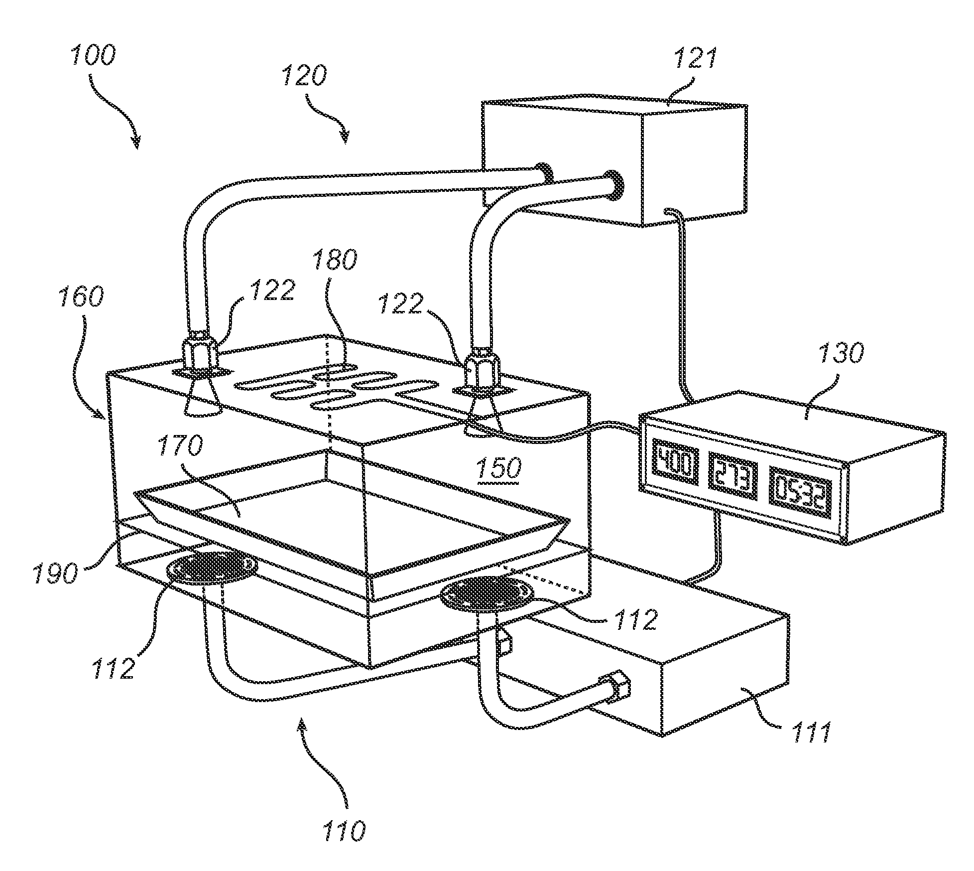
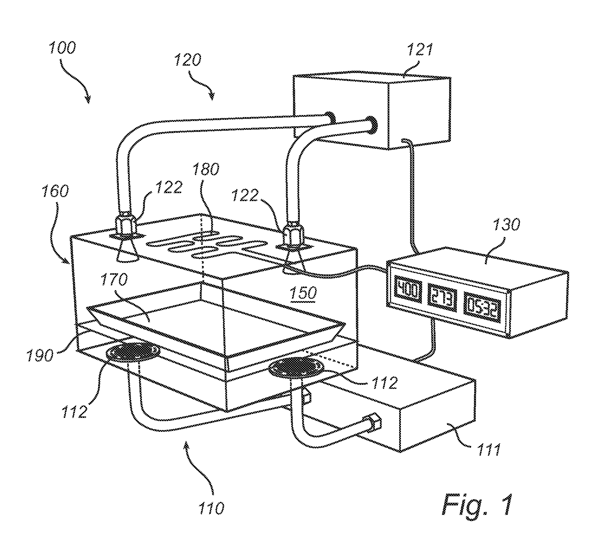
[0028]With reference to FIG. 1, there is shown a microwave heating apparatus 100, e.g. a microwave oven, having features and functions according to an embodiment of the present invention.

[0029]The microwave oven 100 comprises a cavity 150 defined by an enclosing surface or external casing 160. The cavity 150 is arranged to receive a piece of food to be heated and, in particular, may be equipped with a bottom shelf 190 for receiving the piece of food or an accessory 170 containing the piece of food. The bottom shelf 190 may for instance be made of glass.

[0030]The microwave oven further comprises a first microwave supply system 110, a second microwave supply system 120 and a control unit 130 configured to control the first and second microwave supply systems 110 and 120 based on a food category and / or a cooking program.

[0031]The first supply system 110 comprises at least one microwave source 111 (or a generating block comprising a plurality of microwave sources) and at least one anten...


PUM


Abstract

A microwave heating apparatus for heating a load by means of microwaves is provided. The microwave heating apparatus comprises a cavity arranged to receive a piece of food to be heated, a first microwave supply system configured to supply microwaves at the cavity bottom for energizing a browning function in the cavity, a second microwave supply system configured to supply microwaves into the cavity for exciting cavity modes and a control unit configured to control the first and second microwave supply systems based on a food category and / or a cooking program. The first supply system comprises at least one microwave source and at least one antenna arranged in a lower part of the cavity and the second microwave supply system comprises at least one microwave source and at least one feeding port arranged in an upper part of the cavity. The present invention is advantageous in that a microwave heating apparatus with an improved crisp function is provided.

Description

BACKGROUND OF THE INVENTION[0001]The present invention relates to the field of microwave heating and, in particular, to a versatile microwave heating apparatus.FIELD OF THE INVENTION[0002]The art of microwave heating involves feeding of microwave energy into a cavity. Although the basic function of a microwave oven is to heat food by dielectric heating (i.e. via directly acting microwaves absorbed in the food), microwave ovens have been developed to include additional kinds of cooking capabilities, such as e.g. a crisp (or browning) function or a grill function, thereby enabling preparation of various types of food items and providing new culinary effects. Such additional kinds of cooking capabilities usually require additional components such as a browning plate or a grill element.DESCRIPTION OF THE RELATED ART[0003]An example of such a microwave oven is for instance described in American patent U.S. Pat. No. 5,595,673, wherein the microwave oven comprises a magnetron, a browning p...

Claims


Application Information

Patent Timeline
Patent Type & Authority Applications(United States)
IPC IPC(8): H05B6/68
CPCH05B6/6482H05B2206/044H05B6/6494H05B6/6402H05B6/6447
Inventor NIKLASSON, OLLECARLSSON, HAKANNORDH, ULFHALLGREN, FREDRIK
Owner WHIRLPOOL CORP
Learn More