Load bearing devices for human load bearing usages

a technology of load bearings and load bearings, which is applied in the field of correct load bearings, can solve the problems of reducing the flexibility of the device, pinning or jabbering the wearer, etc., and achieves the effect of minimizing or eliminating relative motion and increasing user comfor

Active Publication Date: 2011-12-08
5 11 INC
View PDF28 Cites 3 Cited by
  • Summary
  • Abstract
  • Description
  • Claims
  • Application Information

AI Technical Summary

Benefits of technology

[0012]The embodiments of the disclosed invention solves these problems with embodiments of the invention which include thin, spring-like and semi-rigid plates which preferably approximates the contours of the body in the region of the lateral sides of the pelvis, which have the properties of being stiff enough to distribute point or line loads over a broad area, significantly increasing user comfort and eliminating the need for the user to adjust his / her posture to compensate for pressure points, or other discomforts associated with the load. Still alternatively, embodiments of the invention include spring-like curved plates that do not conform to the body in vertical cross-section and include padding adjacent of the body to conform to the body for comfort.
[0013]Furthermore, in embodiments of the invention, the curvature in the horizontal plane is naturally slightly larger than the wearer's waist, such that when compressed against the body as under a belt, the plate exerts a spring force against the belt away from the body along the length of the plate moving away from the centerline. This unloads the abdominal and spinal areas and applies lateral loads to the sides of the pelvis and the gluteus muscle group, effectively coupling the load to the wearer's pelvis. Correcting the load location frees the wearer from needing to compensate for an incorrectly placed load, typically done by standing in an ergonomically incorrect position. The corrected load is positioned to take the most direct path through the pelvis to the femur and down to the ground. In other embodiments, the spring action of the device has the further quality of applying a larger securing force to the lateral area of the pelvis due to the mechanical reaction force, without extra tightening of the belt thus avoiding the typical result of cutting off circulation and impinging on nerves.
[0014]Embodiments of this invention solve the problem of discontinuity between load elements by being substantially stiff across the entire device, minimizing or eliminating relative motion between the load elements. As the user moves, the independent elements are subjected to different loads, and their relative position is determined only by the belt to which they are attached. Belts universal in this type of application are insufficiently stiff to maintain a consistent relative position of the load elements, and so when subjected to different loading conditions, the elements are free to an extent to move relative to one another, kinematically behaving as a series of loosely coupled masses. This can cause the elements to pinch or jab the wearer and be a contributing factor in injury and discomfort. By holding each load element securely against the device, the individual load elements are fixed relative to one another and can no longer move independently. This has the property of making a multi-element load behave kinematically as a single element load on each hip, whose relative geometry is restricted to the flexibility of the device. More beneficial to user comfort is that the shape to which the elements are constrained is very close to the geometry of the user's hips as described in herein. Furthermore, embodiments of the invention are sufficiently stiff that a reasonably expected point load from a single element will not disrupt the continuity of the main curvature by causing it to locally invert and become convex instead of concave. While the numerical value of the local radius of curvature is not necessarily uniform across the device, it should not grow to infinity, geometrically defined as a flat spot in the curve, or invert as this may cause a local pressure point on the user.

Problems solved by technology

Belts universal in this type of application are insufficiently stiff to maintain a consistent relative position of the load elements, and so when subjected to different loading conditions, the elements are free to an extent to move relative to one another, kinematically behaving as a series of loosely coupled masses.
This can cause the elements to pinch or jab the wearer and be a contributing factor in injury and discomfort.
This has the property of making a multi-element load behave kinematically as a single element load on each hip, whose relative geometry is restricted to the flexibility of the device.

Method used


Image

  • Load bearing devices for human load bearing usages
  • Load bearing devices for human load bearing usages
  • Load bearing devices for human load bearing usages

Examples


Embodiment Construction

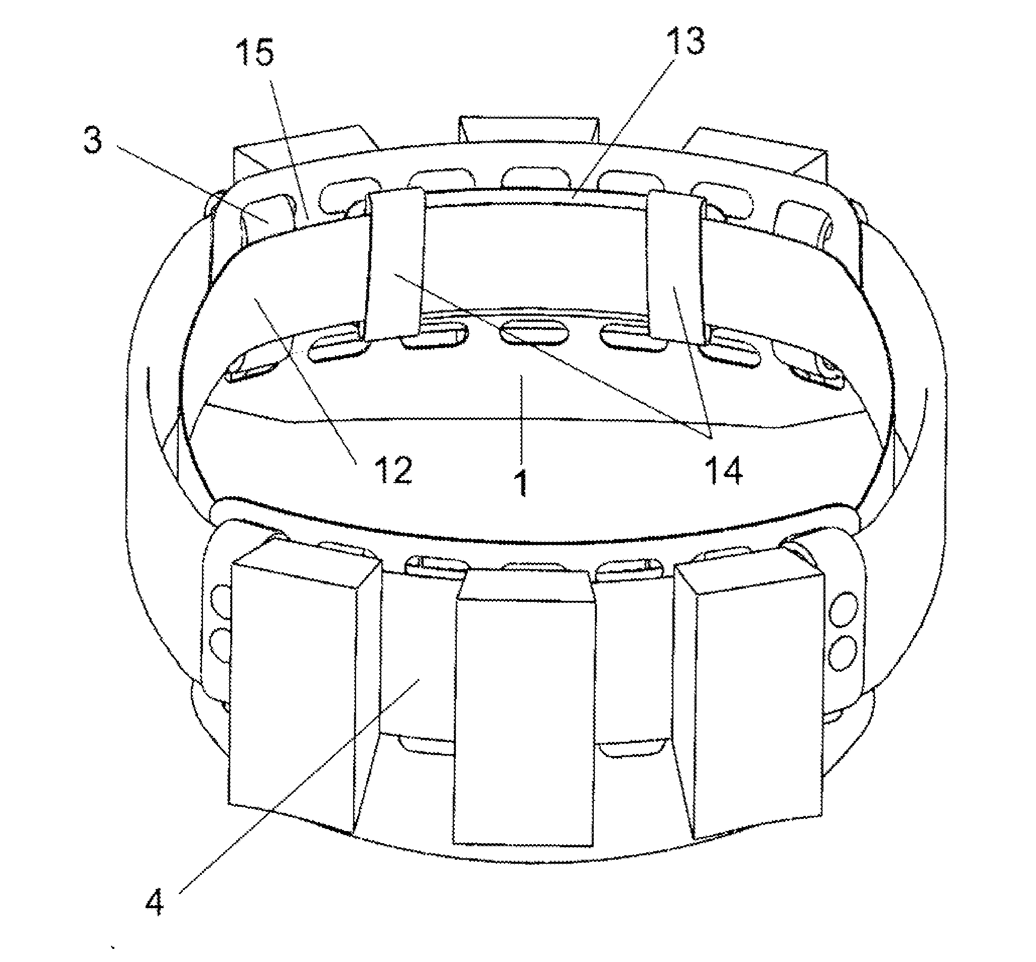
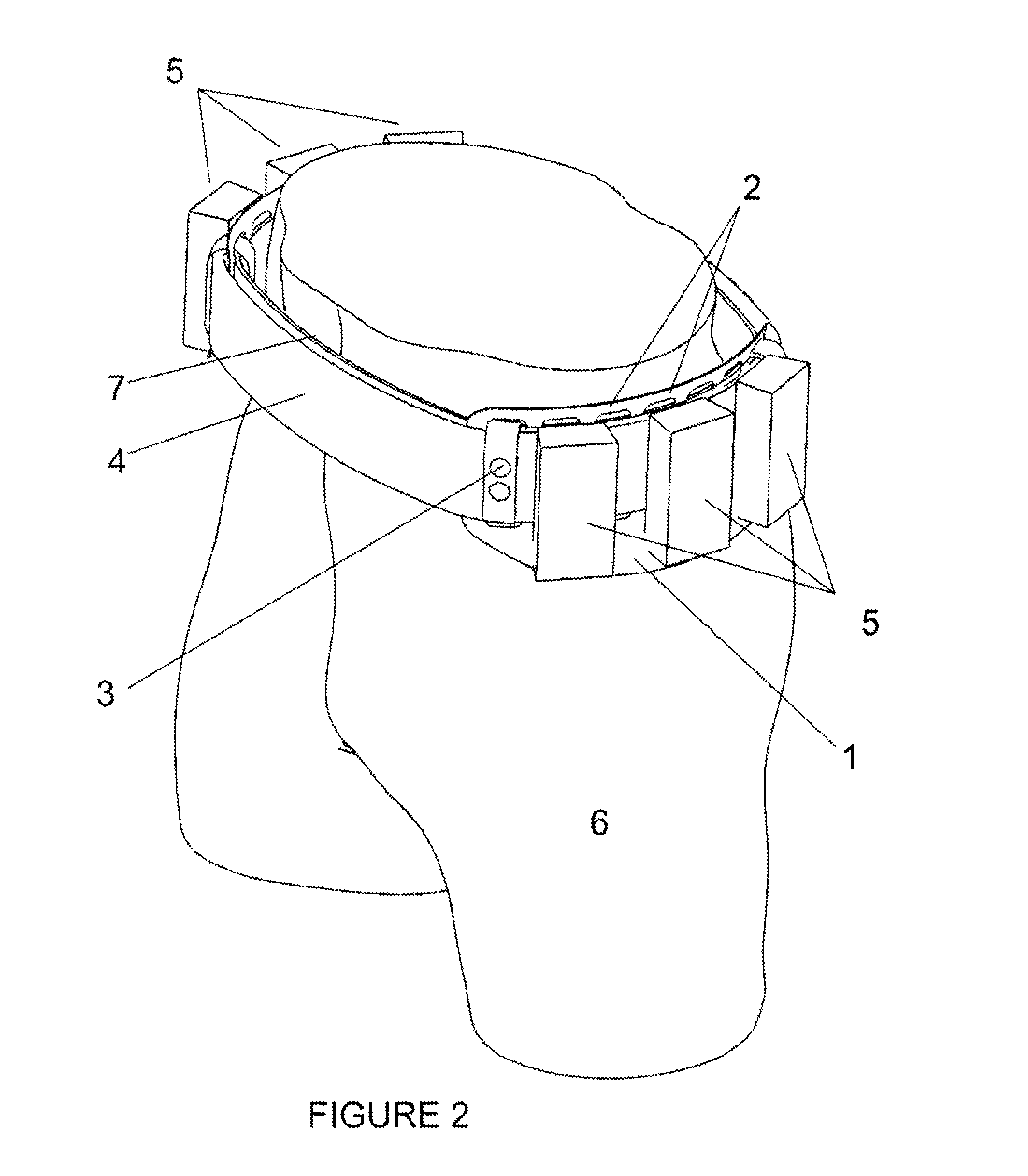
[0027]Preferred embodiments of the invention are set out below. It is to be understood that the embodiments of the invention can be provided separately and then used in conjunction with belts, clothes, backpacks or other load bearing devices suitable for a human to use to carry a load. Further other embodiments of the invention can be incorporated and designed into belts, clothes, backpacks and other load bearing devices suitable for a human to use to carry a load.

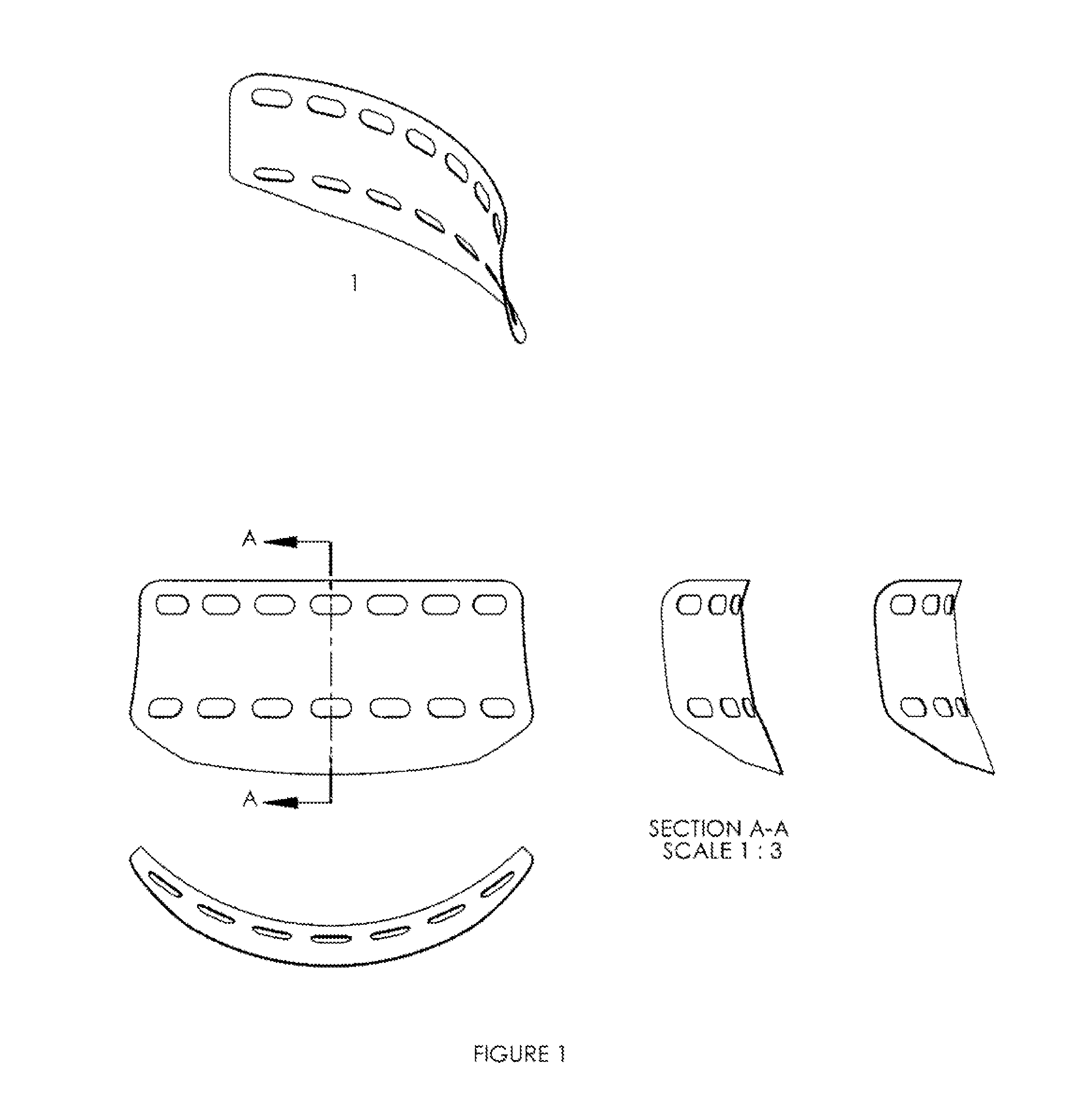
[0028]It is to be understood that although the below embodiment is depicted as including first and second plates, that another embodiment of the invention can have the first and second plates combined into a single plate and be within the spirit and scope of the invention. By way of example only, an embodiment of the single plate design has a connector that maps to the back side of the user and connects the first plate to the second plate. The connector is flexible and adjustable so that the position of the first plate rel...


PUM


Abstract

A load bearing device for human use include first and second load bearing plates that have a first uncompressed position and a second compressed position that conform to the anatomy of the hips of a human. The plates are sufficiently rigid so as to prevent local inversion when the plates are subject to point or line loads and so as to distribute local loads over the plates. The plates can be used with belts, clothes, backpacks and other load carrying devices and can be incorporated into belts, clothes, backpacks and other load carrying devices.

Description

CLAIM OF PRIORITY[0001]This application claims benefit to U.S. Provisional Application No. 61 / 350,583, filed Jun. 2, 2010 entitled “LOAD BEARING DEVICES FOR HUMAN LOAD BEARING USAGES”.FIELD OF INVENTION[0002]The subject invention relates to health equipment, tactical and recreational gear, and relates more specifically to the correct load bearing on human hips.BACKGROUND[0003]Since the invention of tools, men have had to carry them from place to place. The belt was identified early as an optimal place to carry items both for the hip's inherent load bearing ability as well as the quick access provided for weapons and tools. Today, a broad range of professionals still carry their equipment on their hips on a daily basis: police officers, construction workers, and soldiers to name a few. In both recreation and military load bearing, heavy backpacks typically offload significant amounts of weight to the hips in an effort to by-pass the spine.[0004]As tools have become more capable, thos...

Claims


Application Information

Patent Timeline
Patent Type & Authority Applications(United States)
IPC IPC(8): A45C13/30
CPCA45F5/021A45F5/02
Inventor CROMIE, JOHN WILLIAMCOLEMAN, MATTHEW STEPHEN
Owner 5 11 INC
Why Eureka
Try Eureka