Electronic operating device for a gas discharge lamp

a technology of electric operating device and gas discharge lamp, which is applied in the direction of gas discharge lamp usage, climate sustainability, light sources, etc., can solve the problem of inability to use a resonant ignition arrangement, achieve stable operation, avoid acoustic resonance in the lamp, and achieve effective resonance circuit

Inactive Publication Date: 2011-12-08
OSRAM GMBH
View PDF2 Cites 11 Cited by
  • Summary
  • Abstract
  • Description
  • Claims
  • Application Information

AI Technical Summary

Benefits of technology

If the lamp current regulation in the inverter takes place in such a way that the half bridge responsible for the step-down function operates in continuous mode, the ripple current in the lamp inductor becomes small and acoustic resonances in the lamp are avoided. In this case, the momentary value of the lamp current corresponds essentially to the momentary value of the current in the lamp inductor. By virtue of this operating mode, the stimulation of acoustic resonances is prevented in the gas discharge lamp burner, thereby resulting in stable operation.
In this case, the inverter preferably has a lamp inductor and a resonance capacitor, wherein the resonance inductor is embodied as an autotransformer whose center tap is connected to the resonance capacitor. This arrangement provides an effective resonance circuit for the ignition of the lamp. If the current flow through the resonance capacitor can be disconnected by means of a switch that is connected to the resonance capacitor, said switch being contacted during the ignition and take-over of the lamp and then disconnected during the run-up and nominal operation of the lamp, it is possible to ensure an effective and safe operating mode of the circuit arrangement because the resonance circuit is interrupted during the nominal operation.
An intermediate circuit capacitor, which maintains a voltage ripple during the operation, is preferably arranged between the DC / DC voltage converter and the inverter, wherein the AC voltage generated by the inverter is synchronized with the voltage ripple. In this case, the inverter is synchronized relative to the frequency of the voltage ripple in such a way that the AC voltage always commutates in the region of the maximum of the voltage ripple. This measure ensures a high voltage during the commutation, thereby significantly reducing the risk of the gas discharge lamp going out during the commutation.
In a preferred embodiment, the lamp current is preferably square-wave and the height of the lamp current is preferably adapted such that the momentary lamp power in the positive quadrant of the lamp current has the same magnitude as in the negative quadrant of the lamp current. In another preferred embodiment, the sampling ratio of the lamp current is adjusted such that the average lamp power in the positive quadrant of the lamp current has the same magnitude as in the negative quadrant of the lamp current. As a result, the lamp electrodes are heated equally and do not wear asymmetrically.

Problems solved by technology

However, a significant ripple current through the energy store is produced in this operating mode, and therefore the inverter generates an AC voltage of low frequency, onto which a high-frequency AC voltage is modulated.
Since this high-frequency ripple voltage can stimulate acoustic resonances in the burner vessel, it is undesirable and must be filtered before the lamp.
Due to the large filter capacity that is required, however, only a superimposed igniter can be used as an igniter.
The use of an arrangement for resonant ignition is not possible as a result of the large filter capacity.

Method used


Image

  • Electronic operating device for a gas discharge lamp
  • Electronic operating device for a gas discharge lamp
  • Electronic operating device for a gas discharge lamp

Examples


Embodiment Construction

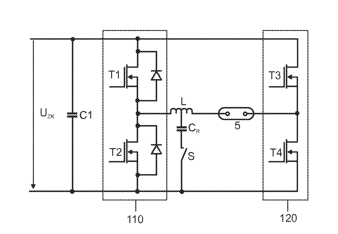
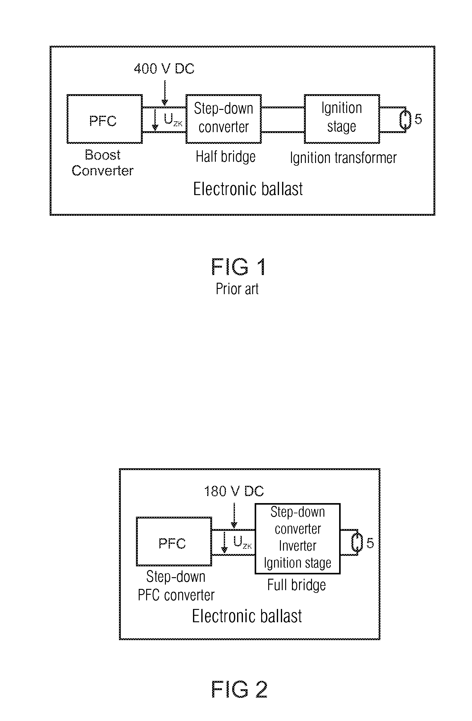
FIG. 2 shows a schematic block diagram of an electronic operating device according to the invention. The electronic operating device according to the invention includes only 2 stages. In the first stage, which contains the DC / DC voltage converter, the input AC voltage is converted into an intermediate circuit voltage UZK of approximately 180 V. For this purpose, the DC / DC voltage converter features a step-down function in addition to the power factor correction, since it reduces the rectified 220 V AC voltage from −325 V to an intermediate circuit voltage UZK of ˜180 V, for example.

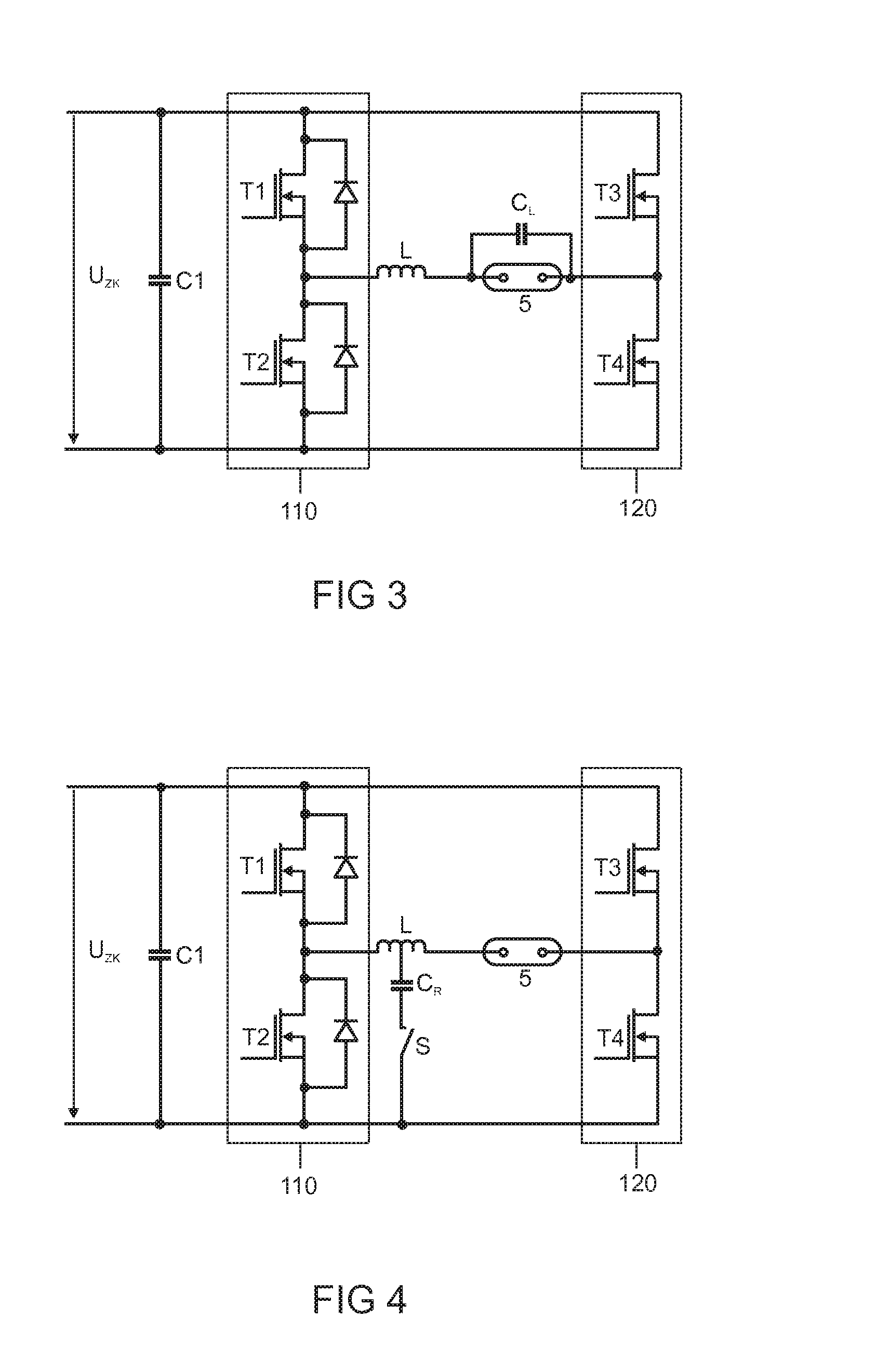
In the subsequent 2nd stage, which features the inverter, the intermediate circuit voltage UZK is converted to a low-frequency AC voltage. A half bridge of the inverter full bridge acts as a step-down switch in this case, reducing the intermediate circuit voltage UZK to the lamp voltage of lower magnitude. The other half bridge of the full bridge operates using a low-frequency AC voltage in this case. In ...


PUM


Abstract

The invention relates to an electronic operating device for a gas discharge lamp having: a DC/DC voltage converter, a power factor correction circuit, an inverter, a lamp inductor, and having a full bridge with two half bridges which can be controlled separately, wherein the DC/DC voltage converter additionally acts as a voltage step-down converter, and the inverter additionally has the following functions: lamp current regulation, the function of stepping down the voltage to the lamp voltage, and resonant ignition.

Description

TECHNICAL FIELDThe invention relates to an electronic operating device for a gas discharge lamp, having a DC / DC voltage converter which features a power factor correction circuit, and having an inverter which features a lamp inductor and a full bridge comprising two half bridges that can be activated separately.PRIOR ARTThe invention takes as its starting point an electronic operating device for a gas discharge lamp, having a DC / DC voltage converter which features a power factor correction circuit, and having an inverter which features a lamp inductor and a full bridge comprising two half bridges that can be activated separately, of the type specified in the main claim.FIG. 1 shows the existing design of an electronic operating device according to the prior art. This consists of three stages: in a first stage including the DC / DC voltage converter, the input AC voltage is stepped up to a so-called intermediate circuit voltage UZK of 400 V. The intermediate circuit voltage UZK is a DC...

Claims


Application Information

Patent Timeline
Patent Type & Authority Applications(United States)
IPC IPC(8): H05B41/26
CPCH05B41/2887Y02B20/202H05B41/2928Y02B20/00H05B41/288H05B41/292
Inventor MUEHLSCHLEGEL, JOACHIM
Owner OSRAM GMBH
Why Eureka
Try Eureka