Check patentability & draft patents in minutes with Patsnap Eureka AI!

Methods and Apparatuses for Delay-Locked Loops and Phase-Locked Loops

Active Publication Date: 2011-12-08
INTEL CORP
View PDF7 Cites 10 Cited by
  • Summary
  • Abstract
  • Description
  • Claims
  • Application Information

AI Technical Summary

Problems solved by technology

This leads to a waste of power usage when the circuitry is inactive.

Method used


Image

  • Methods and Apparatuses for Delay-Locked Loops and Phase-Locked Loops
  • Methods and Apparatuses for Delay-Locked Loops and Phase-Locked Loops
  • Methods and Apparatuses for Delay-Locked Loops and Phase-Locked Loops

Examples


Embodiment Construction

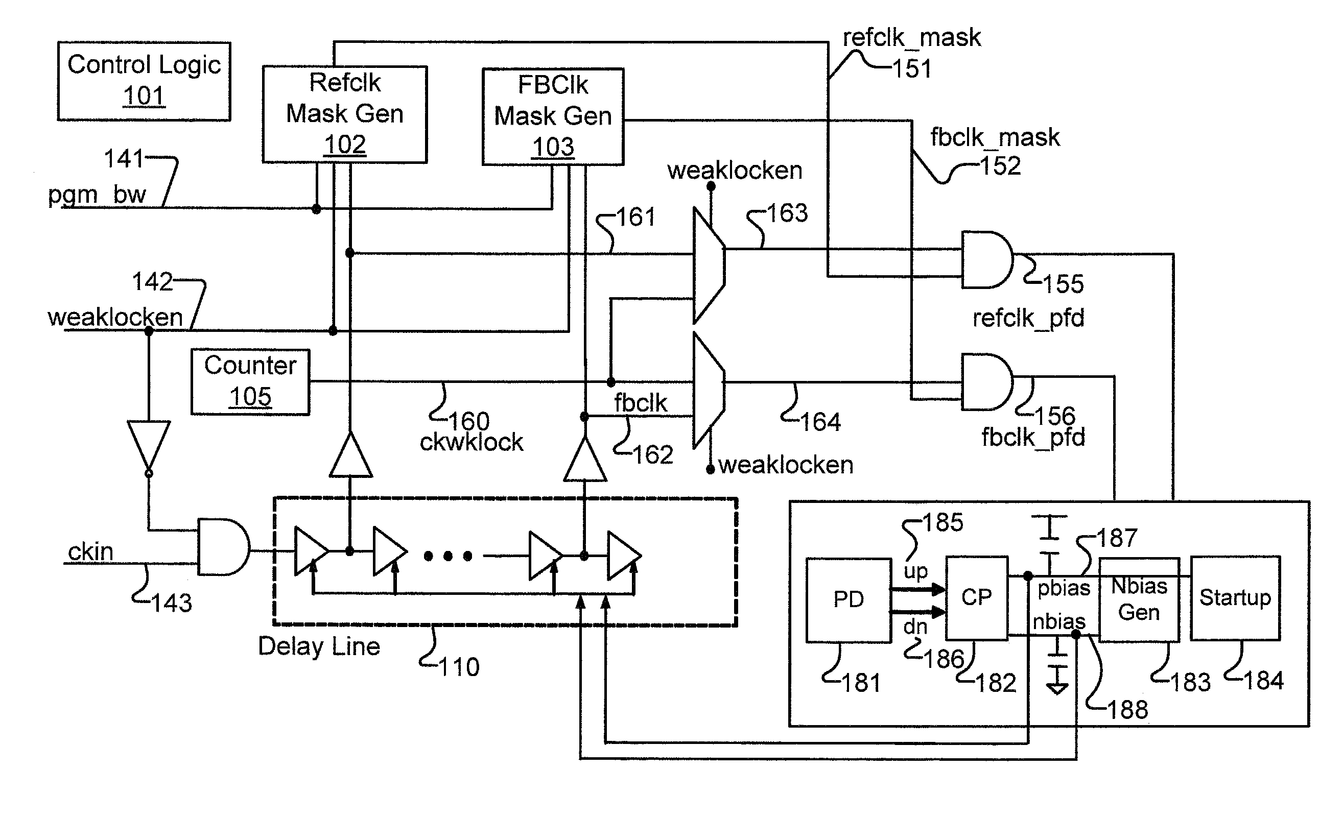
[0012]Methods and apparatuses for delay-locked loops (DLLs) and phase-locked loops (PLLs) are presented with the reference to a delay-locked loop (DLL). In one embodiment, the DLL includes a phase detector which includes a reference input and a feedback input to determine a phase difference. The DLL also includes a controller to determine whether to provide a signal to both the reference input and the feedback input such that the reference input and the feedback input receive an identical input, for example, during low power operation.

[0013]In the following description, numerous details are set forth to provide a more thorough explanation of embodiments of the present invention. It will be apparent, however, to one skilled in the art, that embodiments of the present invention may be practiced without these specific details. In other instances, well-known structures and devices are shown in block diagram form, rather than in detail, in order to avoid obscuring embodiments of the pres...


PUM


Abstract

A low power delay-locked loop (DLL) is presented. In one embodiment, the DLL includes a phase detector which includes a reference input and a feedback input to determine a phase difference. The DLL also includes a controller to determine whether to provide a signal to both the reference input and the feedback input such that the reference input and the feedback input receive an identical input, for example, during low power operation.

Description

FIELD OF THE INVENTION[0001]Embodiments of the invention relate to a delay-locked loop or a phase-locked loop; more particularly, a low power delay-locked loop or a low power phase-locked loop.BACKGROUND OF THE INVENTION[0002]DDR interfaces typically use several DLLs (DLLs) where each DLL drives several phase interpolators (PIs). Each PI is used to provide adjustable delay on a pin or a set of pins to help meet timing constraints.[0003]During a period of inactivity, the DLLs are not shut down because of the long relock time involved (typically on the order of 100-200 ns). Some circuitry only powers down the DLL if the circuitry is shut down for long enough to allow the DLL to relock after being powered up.[0004]In power down modes (e.g., DDR CKE power down), the exit latency frequently cannot be more than 10-20 ns. DLLs are not likely to be powered down if such a requirement exists. The total current consumed by the all the DLLs in a DDR port may be about 100 mA. This leads to a was...

Claims


Application Information

Patent Timeline
IPC IPC(8): H03L7/00H03L7/06
CPCG06F1/324G06F1/3296H03L7/0802Y02B60/1285Y02B60/32Y02B60/1217H03L7/0891H03L7/0812H03L7/143H03L7/104Y02D10/00Y02D30/50G11C8/00G11C7/22H03L7/081
Inventor MOSALIKANTI, PRAVEENKURD, NASSER A.MOZAK, CHRISTOPHER P.
Owner INTEL CORP
Features
  • R&D
  • Intellectual Property
  • Life Sciences
  • Materials
  • Tech Scout
  • Unparalleled Data Quality
  • Higher Quality Content
  • 60% Fewer Hallucinations
Learn More