Image forming apparatus

a technology of image forming apparatus and forming medium, which is applied in the direction of electrographic process apparatus, printing, instruments, etc., can solve the problems of image quality degradation, image formation in a high-humidity state and image formation in a low-humidity state, and increase the amount of water contained in the recording medium. to achieve the effect of reducing image quality degradation

Inactive Publication Date: 2011-12-08
CANON KK
View PDF2 Cites 28 Cited by
  • Summary
  • Abstract
  • Description
  • Claims
  • Application Information

AI Technical Summary

Benefits of technology

[0014]The present invention provides an image forming apparatus which performs image formation by exposing a photosensitive member using light beams and is capable of reducing degradation of image quality that occurs when the rotational speed of a polygon mirror or a photosensitive member is changed.

Problems solved by technology

Further, when humidity in an environment where a recording medium is placed rises, the amount of water contained in the recording medium increases, and hence the size of the recording medium also increases.
For this reason, a problem occurs that an image formed in a high-humidity state and an image formed in a low-humidity state differ from each other in size with respect to the size of a recording medium.
However, when an electrostatic latent image is formed on the photosensitive member by the method disclosed in Japanese Patent Laid-Open Publication No. 2004-25841, there arises the following problem.
Thus, the space intervals between scanning lines formed on the photosensitive member become non-uniform due to change in the rotational speed of the polygon mirror.
Thus, when the rotational speed of the polygon mirror is changed, the quality of an image formed on the recording medium is degraded.

Method used


Image

  • Image forming apparatus
  • Image forming apparatus
  • Image forming apparatus

Examples


first embodiment

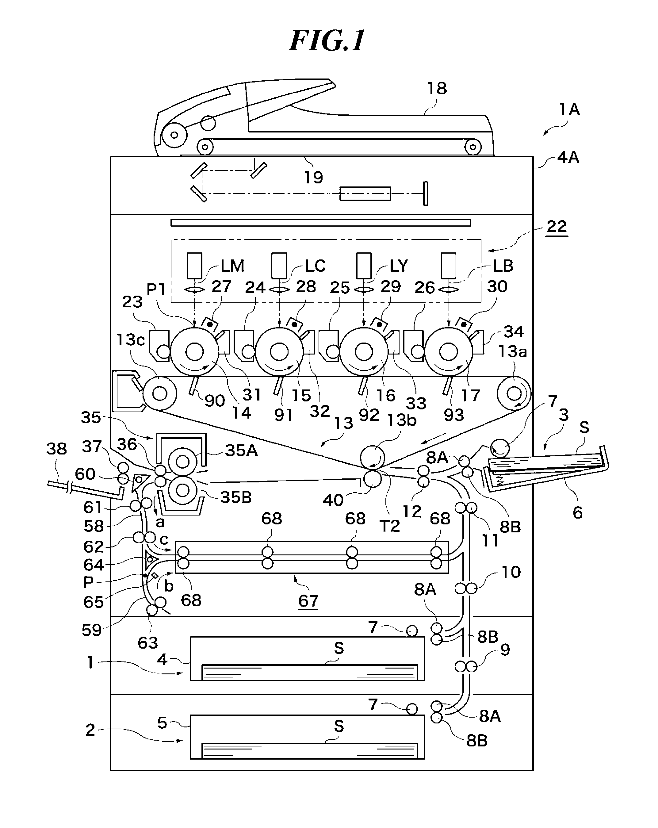
[0046]FIG. 1 is a schematic longitudinal cross-sectional view of an image forming apparatus according to the present invention. Note that the image forming apparatus 1A shown in FIG. 1 is a color image forming apparatus that forms a color image by superimposing four colors of cyan (C), magenta (M), yellow (Y), and black (K) one upon another.

[0047]The image forming apparatus 1A has four photosensitive drums (photosensitive members) 14, 15, 16, and 17. Each of the photosensitive drums 14, 15, 16, and 17 has a surface functioning as an exposed surface. An intermediate transfer belt (endless belt) 13 as an intermediate transfer member is disposed in facing relation to the photosensitive drums 14, 15, 16, and 17. The intermediate transfer belt 13 is stretched around a driving roller 13a, a secondary transfer opposed roller 13b, and a tension roller (driven roller) 13c such that the general shape of the intermediate transfer belt 13 in cross-sectional view is triangular. The intermediate ...

second embodiment

[0125]Next, a description will be given of a variation of the exposure controller of the image forming apparatus according to the present invention. In the present variation, image magnification is changed on each of the front and reverse sides of a recording sheet in the double-sided printing mode, to thereby prevent occurrence of density difference between the front and reverses side of the recording sheet. Note that a controller used in the variation of the exposure controller is identical in configuration to the controller 22B in FIG. 13, but is distinguished from the same by the operation of the CPU 105.

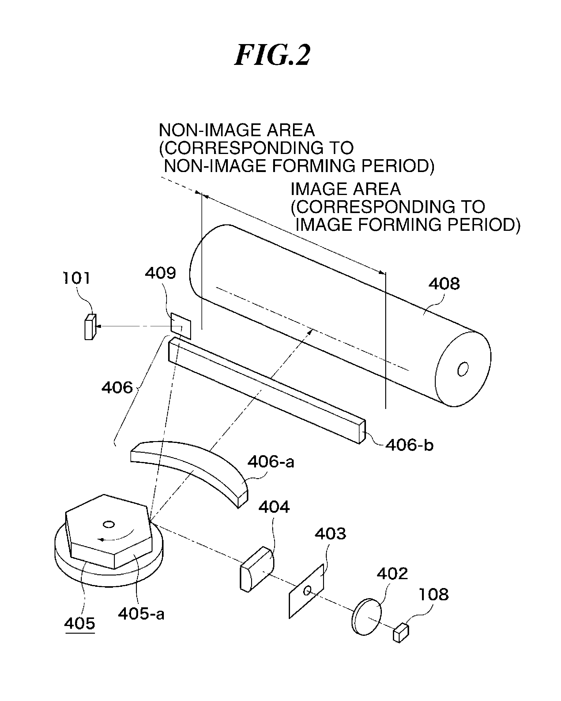
[0126]FIG. 15 is a view illustrating laser spots on a recording sheet before and after magnification correction performed for double-sided printing when exposure is performed by the exposure controller 22 appearing in FIG. 2. Further, FIG. 16 is a diagram illustrating light amount distributions obtained, respectively, in a case where pitches between all the laser spots are unifo...

third embodiment

[0143]FIG. 20 is a block diagram of a controller used in the exposure control section 22 of the image forming apparatus according to the

[0144]The controller shown in FIG. 20 is different in configuration from the controller 22B, shown in FIG. 13, of the exposure control section 22 of the image forming apparatus according to the second embodiment. Therefore, the controller shown in FIG. 20 is denoted by reference numeral 22C. Further, component elements of the controller 22C corresponding to those of the controller 22B in FIG. 13 are denoted by identical reference numerals, and description thereof is omitted.

[0145]In the controller 22C, the CPU 105 and the image processing unit 114 are connected to each other. The image processing unit 114 outputs a light amount correction signal (ON / OFF signal) for causing light amount correction to be executed according to an image pattern in the sub scanning direction. The light amount correction signal is delivered to the CPU 105. When the light ...


PUM


Abstract

An image forming apparatus capable of reducing density variation that occurs in an output image when the rotational speed of a polygon mirror is changed. A light source emits a light beam for forming an electrostatic latent image on a photosensitive drum. The polygon mirror deflects the light beam such that the light beam moves on the photosensitive drum in a predetermined direction. A polygon mirror control circuit controls the polygon mirror such that when the toner image is to be formed at a first magnification, the rotational speed of the polygon mirror is made higher than when the toner image is to be formed at a second magnification that is larger than the first magnification. When the toner image is to be formed at the first magnification, the light beam becomes smaller in light amount than when the toner image is to be formed at the second magnification.

Description

BACKGROUND OF THE INVENTION[0001]1. Field of the Invention[0002]The present invention relates to an image forming apparatus that forms images by exposing a photosensitive member.[0003]2. Description of the Related Art[0004]There has generally been known an image forming apparatus, such as a copying machine or a printer, which performs image formation using the electrophotographic process. In recent years, it has been demanded that an image forming apparatus of this type forms high-quality images on a plurality of types of recording sheets (transfer sheets) at a high speed with high accuracy.[0005]An image forming apparatus using the electrophotographic process is provided with an exposure device that emits a light beam (e.g. a laser beam), and exposes a photosensitive member by the laser beam emitted from the exposure device to thereby form an electrostatic latent image on the photosensitive member. The laser beam is deflected by a rotary polygon mirror (hereinafter simply referred ...

Claims


Application Information

Patent Timeline
Patent Type & Authority Applications(United States)
IPC IPC(8): B41J2/435
CPCG02B26/123G03G15/041G03G2215/0404G03G15/04072
Inventor FURUTA, YASUTOMO
Owner CANON KK
Why Eureka
Try Eureka