Common mode voltage reduction apparatus and method for current source converter based drive

a current source converter and common mode technology, applied in the direction of circuit arrangement, power conversion system, electric power transfer ac network, etc., can solve the problems of not having a fixed voltage dc link, motors are susceptible to damage or performance degradation, common mode control techniques for voltage source converters are not effective for addressing common mode voltages in current source converters, etc., to achieve the effect of facilitating a basic understanding

Active Publication Date: 2011-12-08
ROCKWELL AUTOMATION TECH
View PDF4 Cites 41 Cited by
  • Summary
  • Abstract
  • Description
  • Claims
  • Application Information

AI Technical Summary

Benefits of technology

[0002]Various aspects of the present disclosure are now summarized to facilitate a basic understanding of the disclosure, wherein this summary is not an extensive overview of the disclosure, and is intended neither to identify certain elements of the disclosure, nor to delineate the scope thereof. Rather, the primary purpose of this summary is to present some concepts of the disclosure in a simplified form prior to the more detailed description that is presented hereinafter. The present disclosure provides techniques and apparatus for controlling output common mode voltages by coordination of the rectifier and inverter switching control without requiring isolation or filter components in current source converter drives.

Problems solved by technology

For example, motors are susceptible to damage or performance degradation caused by appearance of excessive common mode voltages on the motor leads.
Current source converters, however, do not have a DC link with fixed voltage, and common mode control techniques for voltage source converters are not effective for addressing common mode voltages in current source converters.

Method used


Image

  • Common mode voltage reduction apparatus and method for current source converter based drive
  • Common mode voltage reduction apparatus and method for current source converter based drive
  • Common mode voltage reduction apparatus and method for current source converter based drive

Examples


Embodiment Construction

[0019]Referring now to the figures, several embodiments or implementations are hereinafter described in conjunction with the drawings, wherein like reference numerals are used to refer to like elements throughout, and wherein the various features are not necessarily drawn to scale.

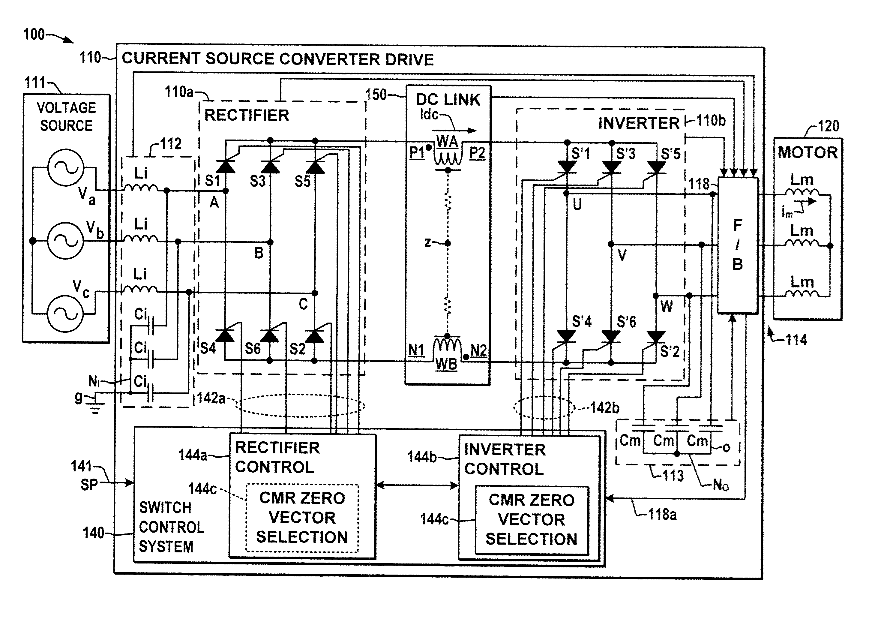
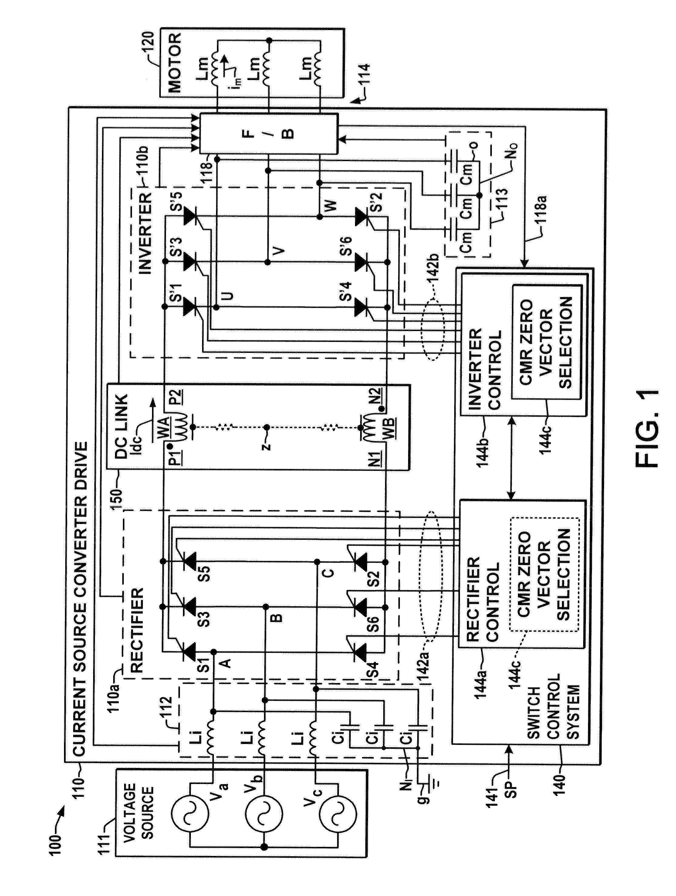
[0020]FIG. 1 illustrates an exemplary power conversion system 100 having a current source converter (CSC) type motor drive 110 driving a motor load 120. The system 100 includes an exemplary three-phase AC voltage source 111 providing input power to the drive 110, and the drive 110 converts the input power to drive a motor load 120 coupled to a converter output 114. The drive 110 is a current source converter (CSC) type, with an input 112 connected to the AC power source 111. While these examples are illustrated as having a three phase input 112, other embodiments may provide a single phase AC input or may include a multiphase input adapted to receive three or more input phases.

[0021]The CSC drive 110 in FI...


PUM


Abstract

Current source converter drives and common mode voltage reduction techniques are presented in which a space vector modulation zero vector for current source inverter (or rectifier) control is selected according to the switching state of the current source rectifier (or inverter) and according to the AC input power and the AC output power to control the output common mode voltage.

Description

BACKGROUND[0001]Motor drives and other forms of power conversion systems convert electrical power from one form to another and may be employed in a variety of applications such as powering an electric motor using power converted from a single or multiphase AC input source. Such power converters are typically constructed using an active rectifier to convert input AC power to an intermediate DC, followed by an active inverter stage that converts the intermediate DC to AC output power to drive a motor, power grid, or other load. The rectifier and inverter include switches actuated through various forms of pulse width modulation (PWM), where the PWM switching states used in the rectifier and inverter may be constructed according to selective harmonic elimination (SHE) or space vector modulation (SVM) or other PWM techniques. Current source converter (CSC) type drives use the rectifier to provide a controlled DC current in an intermediate DC link circuit, which is then converted by the i...

Claims


Application Information

Patent Timeline
Patent Type & Authority Applications(United States)
IPC IPC(8): H02M5/45
CPCH02M1/44H02M2001/123H02M5/4585H02M1/123
Inventor CHENG, ZHONGYUANZARGARI, NAVIDXIAO, YUAN
Owner ROCKWELL AUTOMATION TECH
Why Eureka
Try Eureka