Compact cable suspended pumping system for lubricator deployment

a technology of lubricator and suspension cable, which is applied in the direction of positive displacement liquid engine, sealing/packing, borehole/well accessories, etc., can solve the problems of system length exceeding 200 feet in total length and the inability to retrieve the uni

Inactive Publication Date: 2011-12-08
ZEITECS
View PDF3 Cites 96 Cited by
  • Summary
  • Abstract
  • Description
  • Claims
  • Application Information

AI Technical Summary

Problems solved by technology

There has been limited deployment of cable inserted in coil tubing where the coiled tubing is utilized to support the weight of the equipment and cable, although this system is seen as an improvement over jointed tubing the cost, reliability and availability of coiled tubing units have prohibited use on a broader basis.
Typical electrical submersible pumping systems deployed in high flow rate wells require high horsepower to drive the pump which results in system lengths exceeding 200 feet in total length.
The length of these systems does not allow for the units to be retrieved by a high pressure lubricator for land and offshore installations as such a lubricator would exceed the mast height of the well service rig.

Method used


Image

  • Compact cable suspended pumping system for lubricator deployment
  • Compact cable suspended pumping system for lubricator deployment
  • Compact cable suspended pumping system for lubricator deployment

Examples


Embodiment Construction

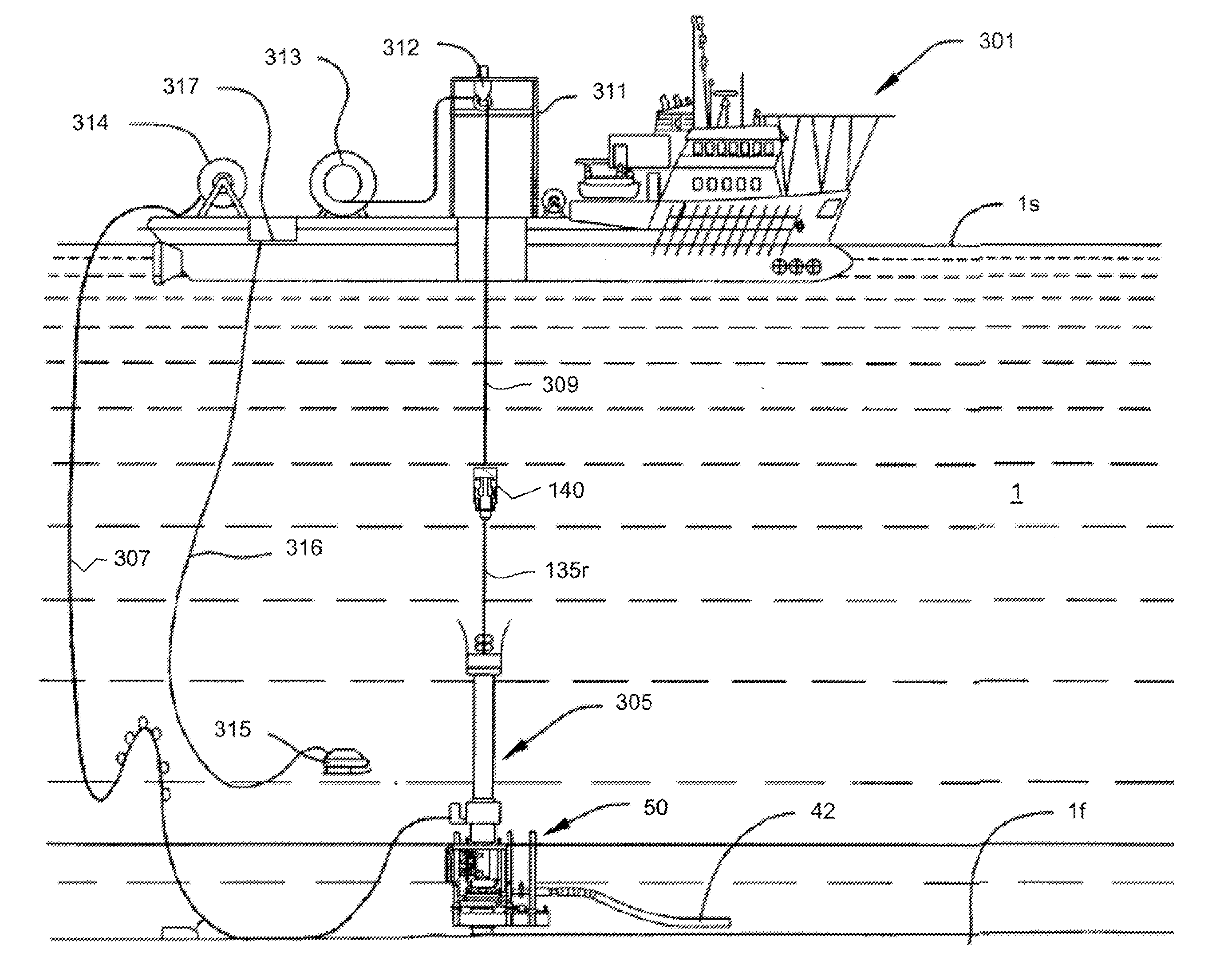
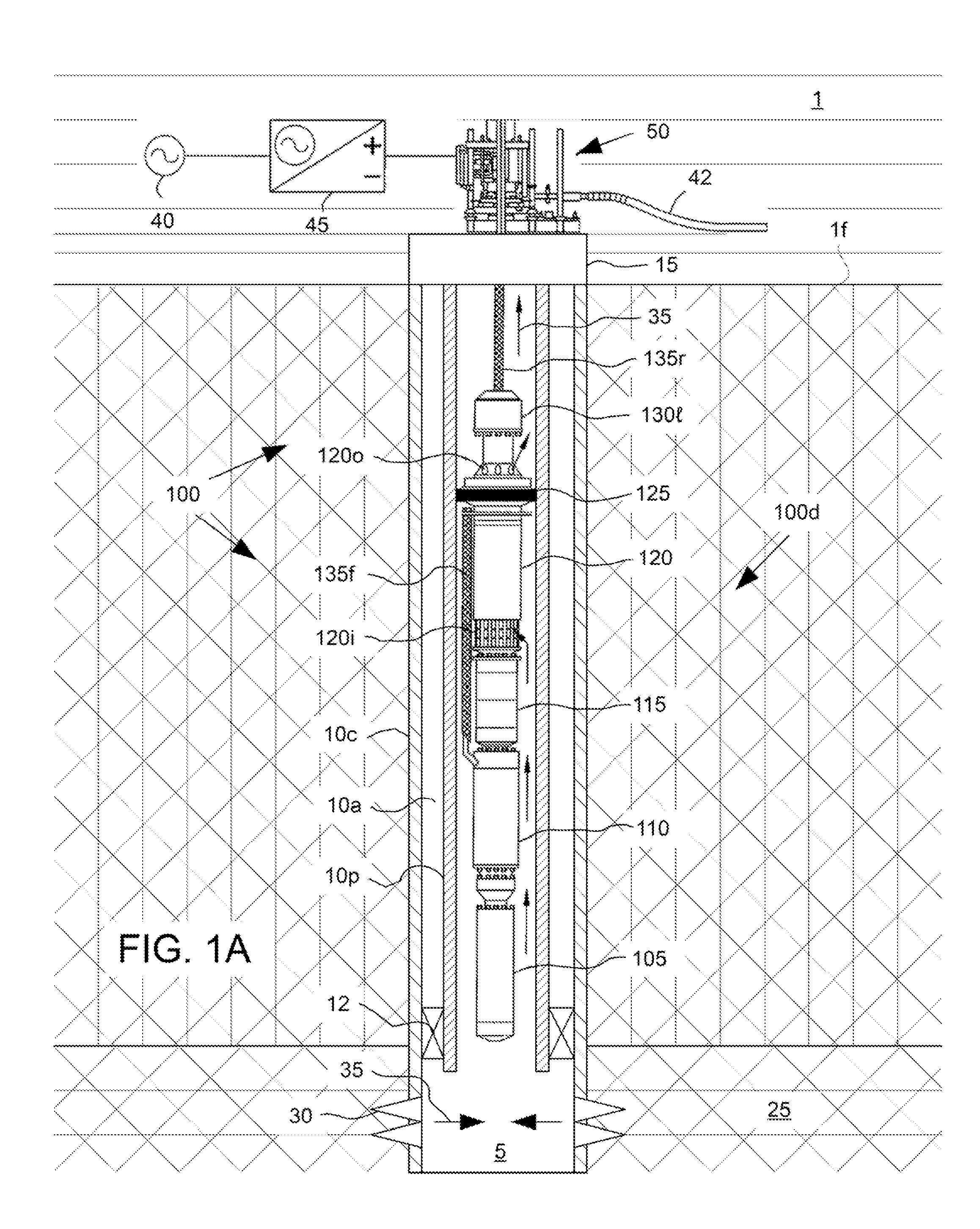
[0017]FIG. 1A illustrates a pumping system, such as an ESP system 100, deployed in a subsea wellbore 5, according to one embodiment of the present invention. The wellbore 5 has been drilled from a floor 1f of the sea 1 into a hydrocarbon-bearing (i.e., crude oil and / or natural gas) reservoir 25. A string of casing 10c has been run into the wellbore 5 and set therein with cement (not shown). The casing 10c has been perforated 30 to provide to provide fluid communication between the reservoir 25 and a bore of the casing 10c. A wellhead 15 has been mounted on an end of the casing string 10c. A string of production tubing 10p may extend from the wellhead 15 to the formation 25 to transport production fluid 35 from the formation to the seafloor 1f. A packer 12 may be set between the production tubing 10p and the casing 10c to isolate an annulus 10a formed between the production tubing and the casing from production fluid 35.

[0018]A subsurface safety valve (SSV) (not shown) may be assembl...


PUM


Abstract

A method of installing or retrieving a pumping system into or from a live wellbore includes connecting a lubricator to a production tree of the live wellbore and raising or lowering one or more downhole components of the pumping system from or into the wellbore using the lubricator.

Description

BACKGROUND OF THE INVENTION[0001]1. Field of the Invention[0002]Embodiments of the present invention generally relate to a compact cable suspended pumping system for lubricator deployment.[0003]2. Description of the Related Art[0004]The oil industry has utilized electric submersible pumps (ESPs) to produce high flow-rate wells for decades, the materials and design of these pumps has increased the ability of the system to survive for longer periods of time without intervention. These systems are typically deployed on the tubing string with the power cable fastened to the tubing by mechanical devices such as metal bands or metal cable protectors. Well intervention to replace the equipment requires the operator to pull the tubing string and power cable requiring a well servicing rig and special spooler to spool the cable safely. The industry has tried to find viable alternatives to this deployment method especially in offshore and remote locations where the cost increases significantly...

Claims


Application Information

Patent Timeline
Patent Type & Authority Applications(United States)
IPC IPC(8): F04B47/06E21B33/035F01C1/16E21B23/00
CPCE21B19/002E21B33/076E21B43/128E21B33/072F04D13/10F04D29/606F04D27/00F04B47/02
Inventor FIELDER, LANCE I.CROWLEY, MATTHEW
Owner ZEITECS
Why Eureka
Try Eureka