Method for generating a bit vector

a bit vector and vector technology, applied in the field of bit vector generation, can solve problems such as reducing the efficiency of these operations

Active Publication Date: 2011-12-08
ROBERT BOSCH GMBH
View PDF3 Cites 5 Cited by
  • Summary
  • Abstract
  • Description
  • Claims
  • Application Information

AI Technical Summary

Benefits of technology

[0016]Additional parity bits of the input signals ensure that switching is performed in the state machines at least once between the different linear transmission functions and thus there is a transmission...

Problems solved by technology

Mask generation therefore does not reduce the efficiency of these operatio...

Method used


Image

  • Method for generating a bit vector
  • Method for generating a bit vector
  • Method for generating a bit vector

Examples


Embodiment Construction

[0039]The exemplary embodiments and / or exemplary methods of the present invention is illustrated schematically in the drawings on the basis of specific embodiments and is described in detail below with reference to the drawings.

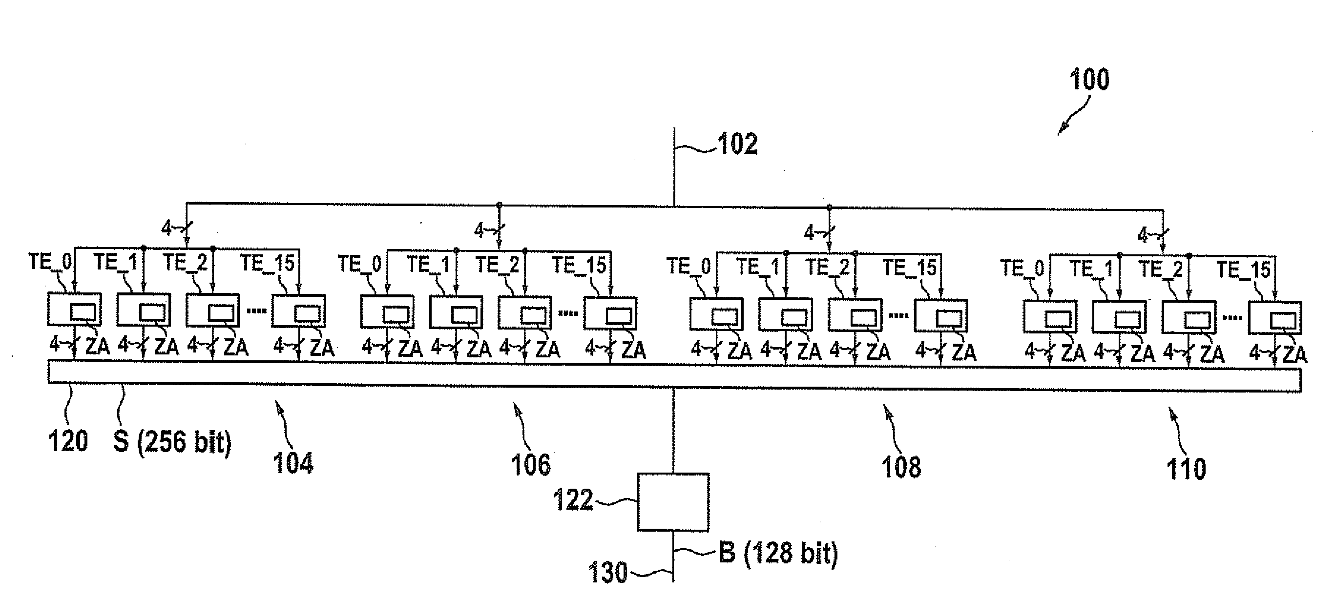
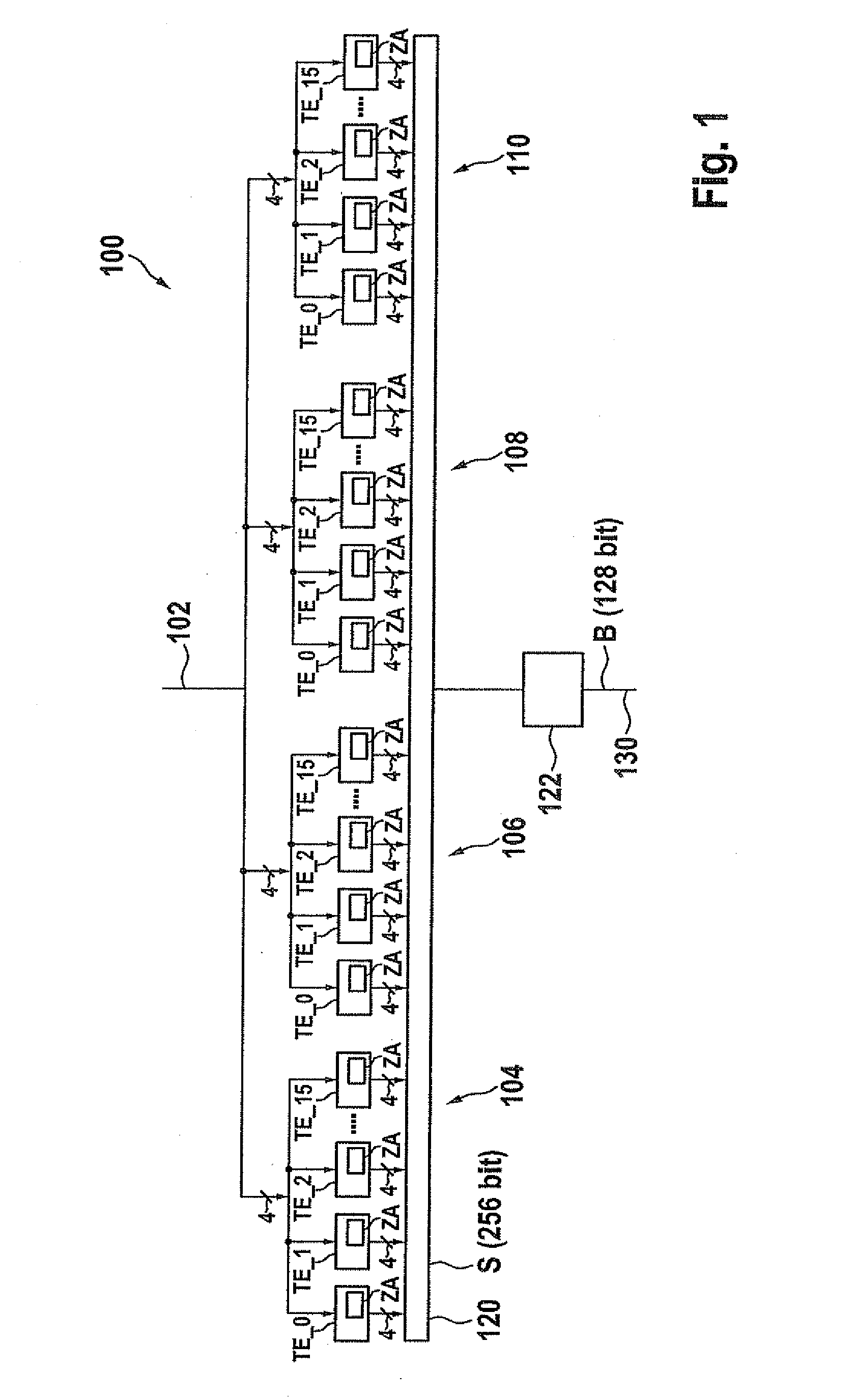
[0040]FIG. 1 schematically shows a specific embodiment of a circuit configuration according to the present invention, which is labeled on the whole with reference numeral 100. This circuit configuration 100 is used to form a bit vector having 128 bits from an input signal 102. For this purpose, circuit configuration 100 includes four configurations 104, 106, 108 and 110, each having sixteen transformation elements TE_0, TE_1, TE_2, . . . , TE_15. For the sake of simplicity, FIG. 1 shows only four of the sixteen transformation elements TE_0, TE_1, TE_2, . . . , TE_15. In this embodiment, circuit configuration 100 is designed in such a way that the same input data or same input signal 102 are / is sent to each transformation element TE_0, TE_1, TE_2, . . . , TE_1...


PUM


Abstract

A method and a circuit configuration for generating a bit vector are described. At least two configurations, each having state machines of the same design, are used, to whose inputs an input signal is sent and which generate an output signal as a function of their state, each state machine always having a different state than the other state machine of one configuration, so that the bit vector is generated by a linear gating of the output signals of the state machines of different configurations.

Description

RELATED APPLICATION INFORMATION[0001]The present application claims priority to and the benefit of German patent application no. 10 2010 029 735.6, which was filed in Germany on Jun. 7, 2010, the disclosure of which is incorporated herein by reference.FIELD OF THE INVENTION[0002]The present invention relates to a method for generating a bit vector and a circuit configuration for performing the method.BACKGROUND INFORMATION[0003]Cryptographic devices and cryptologic algorithms are exposed to attacks in which protected data are to be read or manipulated. With the encryption methods customary today, for example, the Advanced Encryption Standard (AES), the keys used are not ascertainable by trial and error (so-called brute force attacks), even using high-speed computer technology, because the keys are at least 128 bits long. An attacker will therefore also investigate the side effects of an implementation, such as the variation of the power consumption over time, the duration or electro...

Claims


Application Information

Patent Timeline
IPC IPC(8): G06F21/00
CPCH04L2209/046H04L9/003
Inventor BOEHL, EBERHARD
Owner ROBERT BOSCH GMBH
Why Eureka
Try Eureka