Annular Heat Exchanger

a heat exchanger and annular technology, applied in indirect heat exchangers, machines/engines, lighting and heating apparatus, etc., can solve the problems of limiting the ability to control the temperature of exhaust components upstream of the heat recovery device, downstream of the catalytic converter, and increasing the cost and weight of the vehicl

Active Publication Date: 2011-12-15
DANA CANADA CORP
View PDF12 Cites 37 Cited by
  • Summary
  • Abstract
  • Description
  • Claims
  • Application Information

AI Technical Summary

Benefits of technology

[0011]In yet another aspect, the radially inwardly extending wall portion of the intermediate shell has an opening which is selectively opened and closed by a valve, wherein opening of the valve permits direct flow communication between the first and second gas flow openings through the inner gas flow passage, thereby providing a bypass flow passage for the gas. The complete closing of the valve substantially prevents direct flow communication between the first and second gas flow openings through the inner gas flow passage.

Problems solved by technology

Series arrangement of individual exhaust components is wasteful of space, may increase the cost and weight of the vehicle, and limits the ability to control the temperature of exhaust components upstream of the heat recovery device.
While the Yamada et al. device provides a central bypass flow path and thereby eliminates the need for an external bypass, its installation downstream of the catalytic converter (FIG. 6 of Yamada et al.) fails to address the other issues noted above.

Method used


Image

  • Annular Heat Exchanger
  • Annular Heat Exchanger
  • Annular Heat Exchanger

Examples


first embodiment

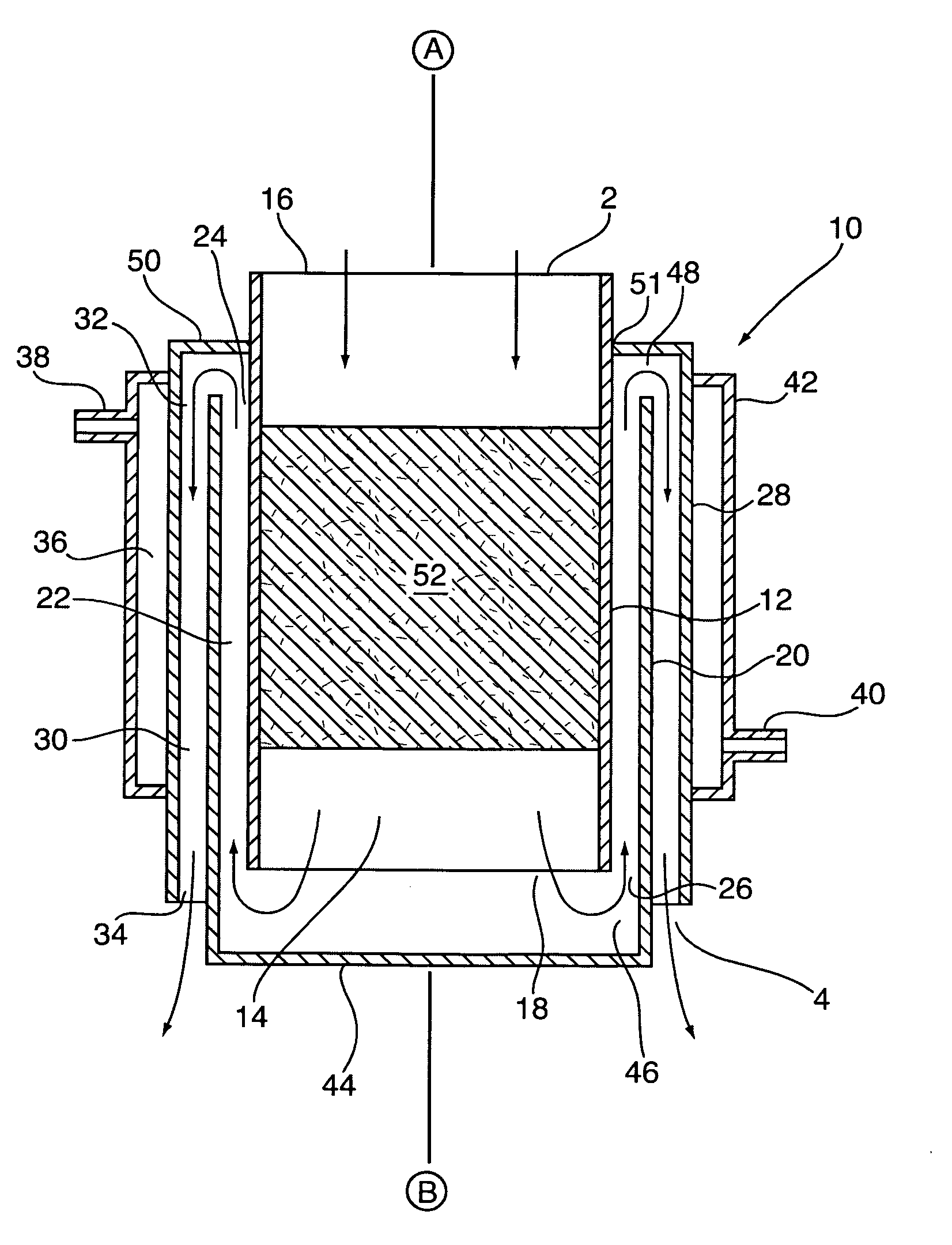
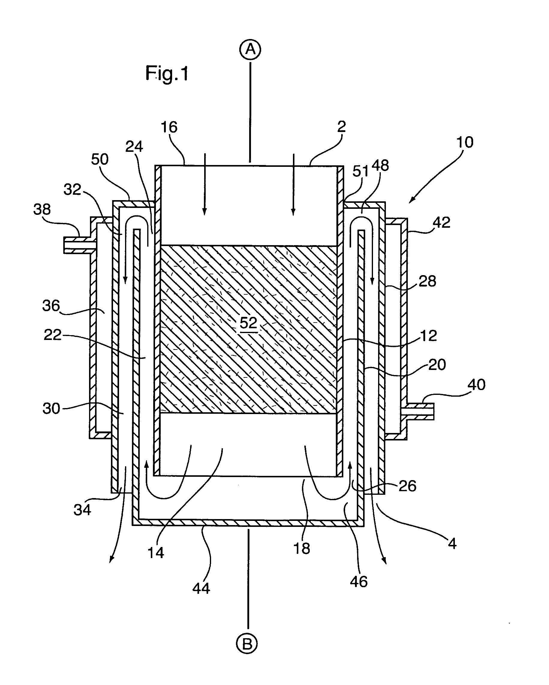
[0028]Illustrated in FIG. 1 is an annular heat exchanger 10 according to the invention. Heat exchanger 10 is generally in the shape of an open-ended, hollow cylinder having a side wall which is comprised of a plurality of cylindrical layers. The side wall of heat exchanger 10 extends parallel to a longitudinal axis A-B passing centrally through the hollow interior space of heat exchanger 10. The heat exchanger 10 includes a number of gas flow passages, described in detail below, and the direction of gas flow through each of the gas flow passages is shown by the arrows in FIG. 1. Although the overall direction of gas flow through heat exchanger 10 is from A to B along axis A-B, it can be seen that there are two changes in the direction of flow as the gas flows through the heat exchanger 10.

[0029]In the following description, the heat exchanger 10 and the various gas flow passages defined therein are described as having a first end and a second end. In the embodiment of FIG. 1, the fi...

second embodiment

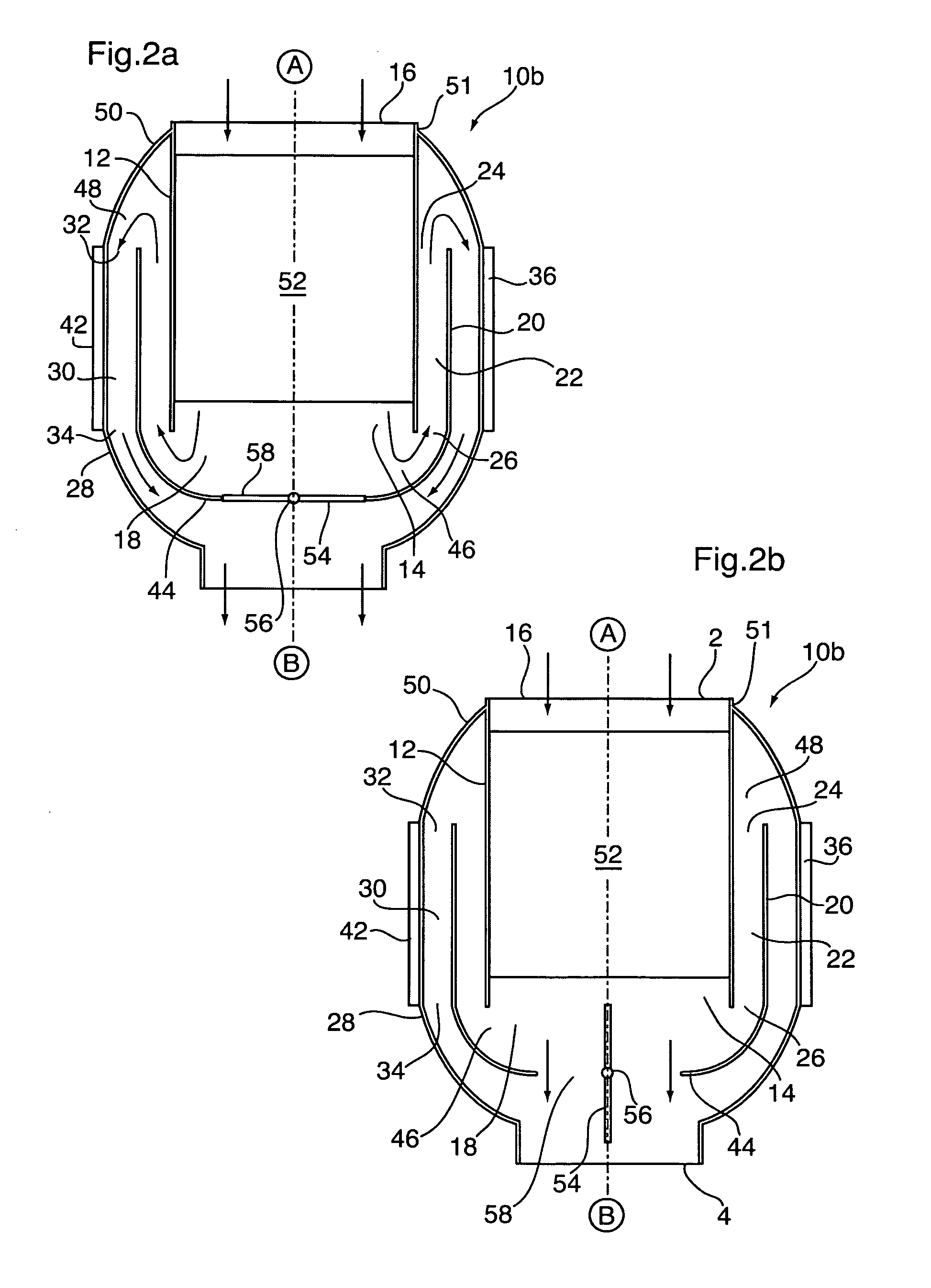
[0044]In some embodiments of the invention, some or all of the gas flow is allowed to selectively bypass the intermediate and outer gas flow passages 22, 30, and thereby flow through heat exchanger 10 without being significantly cooled by the liquid coolant in coolant passage 36. FIGS. 2a and 2b schematically illustrate a heat exchanger 10b according to the invention. Heat exchanger 10b is similar to heat exchanger 10 described above and includes a number of components which are similar or identical to the components of heat exchanger 10. Therefore, the components of heat exchanger 10b are identified with like reference numerals, and the above description of the elements of heat exchanger 10 apply equally to like elements of heat exchanger 10b.

[0045]The heat exchanger 10b differs from heat exchanger 10 in that the inwardly extending wall portion 44 of the intermediate shell 20 is provided with a bypass valve including a valve element 54 which can be partly or completely opened. The...

third embodiment

[0051]FIGS. 3 to 6 illustrate a heat exchanger 100 in accordance with the invention. Heat exchanger 100 incorporates many of the same elements as are present in heat exchangers 10 and 10b described above. Accordingly, these like elements of heat exchanger 100 are numbered using like reference numerals and the above description of the elements of heat exchanger 10 applies equally to like elements of heat exchanger 100.

[0052]Heat exchanger 100 is integrated with a catalytic converter and, as shown in FIG. 4, is comprised of two main sections: a heat exchange and catalytic converter section 93, and a liquid-cooled valve section 94. Heat exchanger 100 is similar to heat exchangers 10 and 10b shown above in that it includes an inner shell 12 (also serving as the catalytic converter housing), an intermediate shell 20 surrounding the inner shell 12, an outer shell 28 surrounding the intermediate shell 20, and a cooling jacket 42 surrounding the outer shell 28. The overall direction of gas ...


PUM


Abstract

An annular heat exchanger for cooling hot gases comprises an inner shell, an intermediate shell and an outer shell. Where the heat exchanger is integrated with a catalytic converter for treatment of hot exhaust gases in a motor vehicle, the inner shell contains a catalyst for treatment of the exhaust gases. Inner and outer gas flow passages are provided between the shells, and a coolant flow passage is provided, either on the outer surface of the outer shell, or inbetween the intermediate and outer shells. The exhaust gases change direction twice as they pass through the heat exchanger, and the annular structure of the heat exchanger provides a large surface area, and a large flow section, relative to volume, and thereby provides effective heat exchange without significantly increasing space requirements.

Description

FIELD OF THE INVENTION[0001]The invention relates to annular heat exchangers for use in removing heat from a gas stream, particularly for use in cooling hot exhaust gas or charge air in a motor vehicle.BACKGROUND OF THE INVENTION[0002]The need to remove heat from gas streams arises in numerous applications. In motor vehicles, for instance, it may be necessary to remove heat from the intake and / or exhaust gas streams. For example, intake air (or “charge air”) requires cooling in some applications, for example in turbocharged or supercharged engines. In vehicles incorporating exhaust gas recirculation (EGR) or exhaust gas heat recovery (EGHR) systems, heat is removed from the exhaust gas stream. The heat removed from the intake or exhaust gas stream is typically transferred to a liquid coolant in a heat exchanger.[0003]In motor vehicle exhaust applications, heat recovery devices are usually located in series with other under-vehicle exhaust components such as catalytic converters. Ser...

Claims


Application Information

Patent Timeline
Patent Type & Authority Applications(United States)
IPC IPC(8): F01N3/02F01N3/28F28D15/00
CPCF01N3/2889F01N2240/36F28D7/103F28D9/0012Y02T10/26F28F27/02F28F2250/06F01N3/2046F28D7/12F28F13/06Y02A50/20Y02T10/12F28D7/02F28D7/10F28F13/00F28F13/02F28F27/00
Inventor BURGERS, JOHN G.MARTIN, MICHAEL A.GERGES, IHAB EDWARDPALANCHON, HERV+E,ACU E+EE
Owner DANA CANADA CORP
Why Eureka
Try Eureka