Apparatus and process for wrapping and securing edge flaps of flexible cover sheet to panel structure

Active Publication Date: 2011-12-15
HAWORTH SPA
View PDF2 Cites 10 Cited by
  • Summary
  • Abstract
  • Description
  • Claims
  • Application Information

AI Technical Summary

Benefits of technology

[0008]In the apparatus as aforesaid, the wiping blades are preferably plate-like members constructed of an elastomeric or rubber-like material having limited flexibility, with the protruding or cantilevered outer tip edge preferably being slightly rounded and having limited elastic deflectability so as to be capable of engaging the edge flap and pushing it into snug contacting and hence adhesive engagement with the underlying frame surface, while at the same time avoiding undesired frictional contact and possibly damaging surface contact with the covering sheet. The wiping blade, particularly when oriented generally vertically and moved horizontally so as to engage the flap for pressed engagement against the upward-facing back face, enables the edge part of the flap to be pressed snugly downwardly into contact with the back face at a location closely adjacent a corner defined with the upwardly protruding rib, thereby maximizing the contact area between the edge flap and the back surface, and greatly minimizing the possibility of the edge portion of the edge flap being free and unsecured.

Problems solved by technology

While constructions of this type are conventionally utilized, the construction of such panels and specifically the application of a thin flexible covering sheet to the pad substrate has long been an undesirably inefficient and costly process requiring a high degree of manual labor and manipulation in order to ensure that the flexible covering sheet is properly attached to its underlying substrate in a manner which ensures proper alignment of the covering sheet while at the same time avoiding undesired looseness, puckering or wrinkling.
As noted above, this is a time consuming and hence costly manual assembly process.
While this apparatus, as disclosed in co-pending U.S. Ser. No. 11 / 369,171, has been successfully adopted for folding and securing edge flaps of a covering sheet to the back sides and / or edges of panels and pads, nevertheless this apparatus possesses structural and operational characteristics which are not optimally suited for all panel or pad constructions.
Wrapping an edge flap around the edge surface and onto the back surface, and then effecting proper adhesive securement thereof to the back surface, is difficult since the pressing rollers of the above-described apparatus are incapable of effecting pressing of the edges of the cover sheet flaps into corners adjacent the protruding fasteners or ribs.
In addition, the rollers associated with the above-described apparatus typically simultaneously cooperate with opposed edges to effect holding of the panel during the pressing of the opposite edge flaps, particularly since the movement of the rollers upwardly and then over onto the back face prevents or greatly restricts proper clamping of the panel since engaging top clamps to the edge frame members is effectively prohibited due to the clearance space required by the pressing rollers.
This known apparatus, as described above, hence possesses operational characteristics which are either not suited or inconvenient for use with certain panel constructions, particularly those employing a rearwardly protruding rib or fastener associated with the back surface of the frame and spaced inwardly a relatively small distance from the adjacent edge surface.

Method used


Image

  • Apparatus and process for wrapping and securing edge flaps of flexible cover sheet to panel structure
  • Apparatus and process for wrapping and securing edge flaps of flexible cover sheet to panel structure
  • Apparatus and process for wrapping and securing edge flaps of flexible cover sheet to panel structure

Examples


Embodiment Construction

[0033]Referring initially to FIGS. 18-20, there is illustrated one embodiment of a known workpiece or substrate 10 which is used for forming an upholstered article such as a pad or panel structure 21, typically for attachment to a frame structure for defining an upright space-dividing wall.

[0034]The workpiece or substrate 10 includes a generally stiff or fairly rigid core 11 which has a sheet-like or plate-like configuration defined by rather large front and back sides, with the core 11 having a thickness which is small in comparison to its other (i.e. length and width) dimensions. The core 11, which may comprise a wall board panel, is supported and surrounded by a rigid ring-shaped frame 12 defined by generally parallel side frame elements 13 which extend along one pair of opposite sides of the core, with the side frame elements 13 being rigidly joined by generally parallel elongate side frame elements 14 which extend along the remaining parallel sides of the core. The elongate sid...


PUM

PropertyMeasurementUnit
Angleaaaaaaaaaa
Flexibilityaaaaaaaaaa
Adhesivityaaaaaaaaaa

Abstract

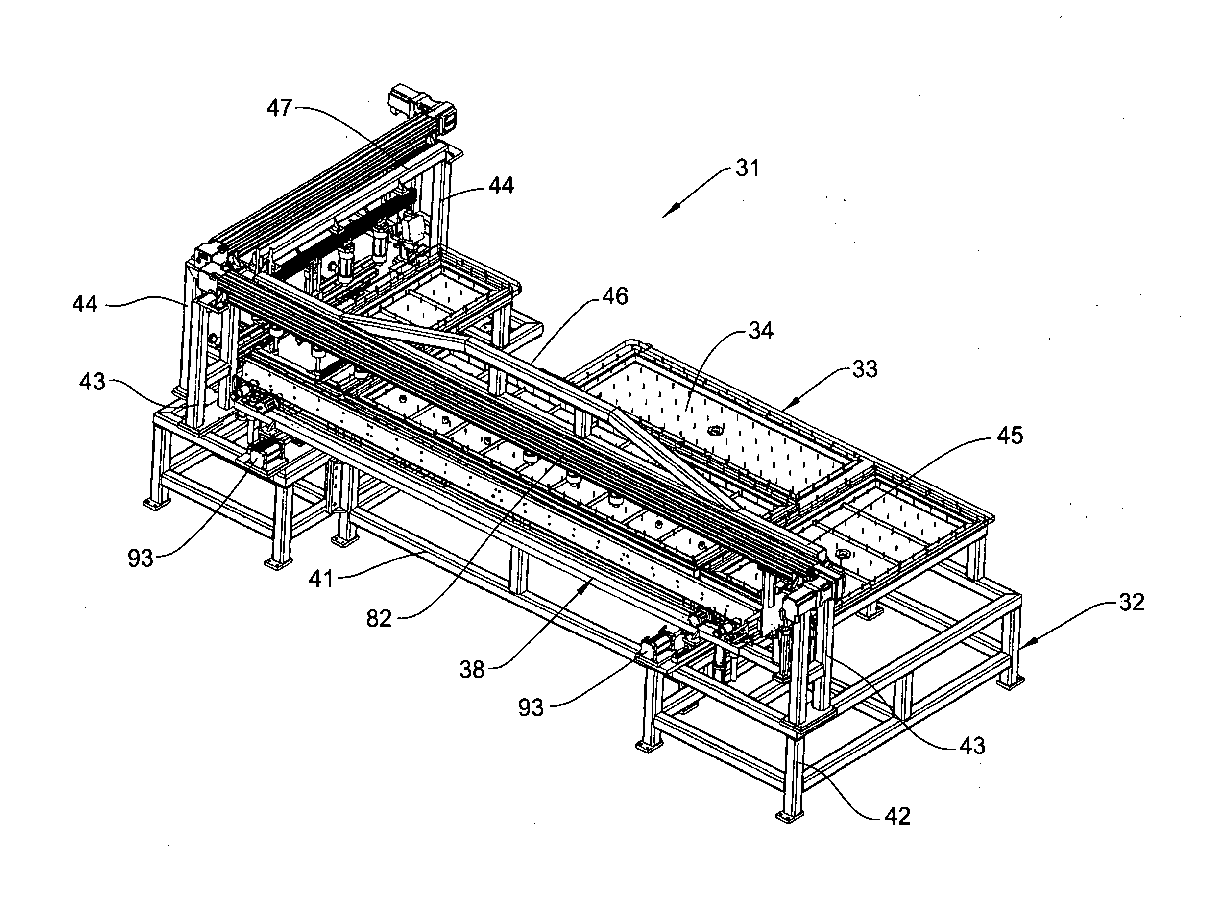
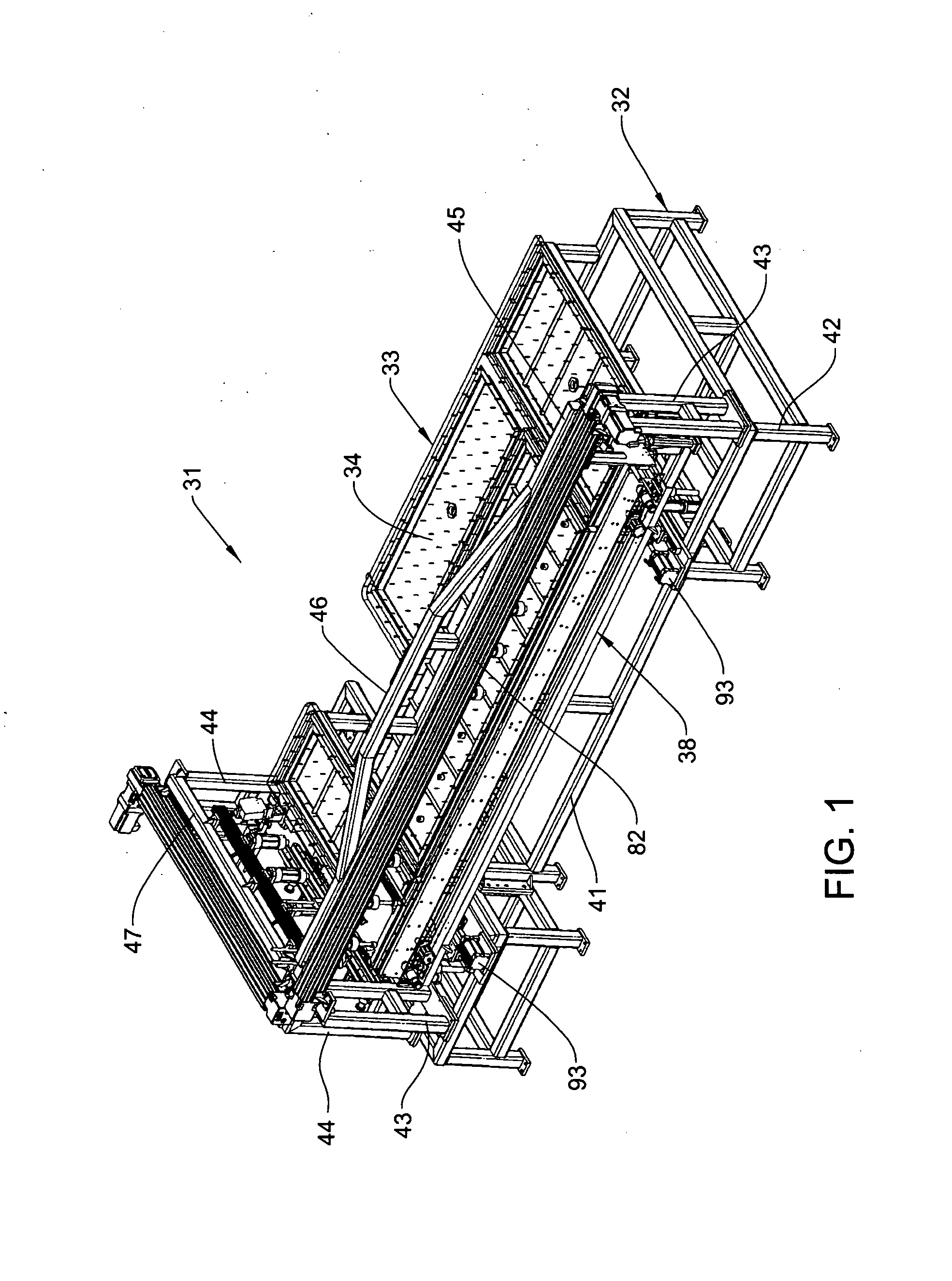
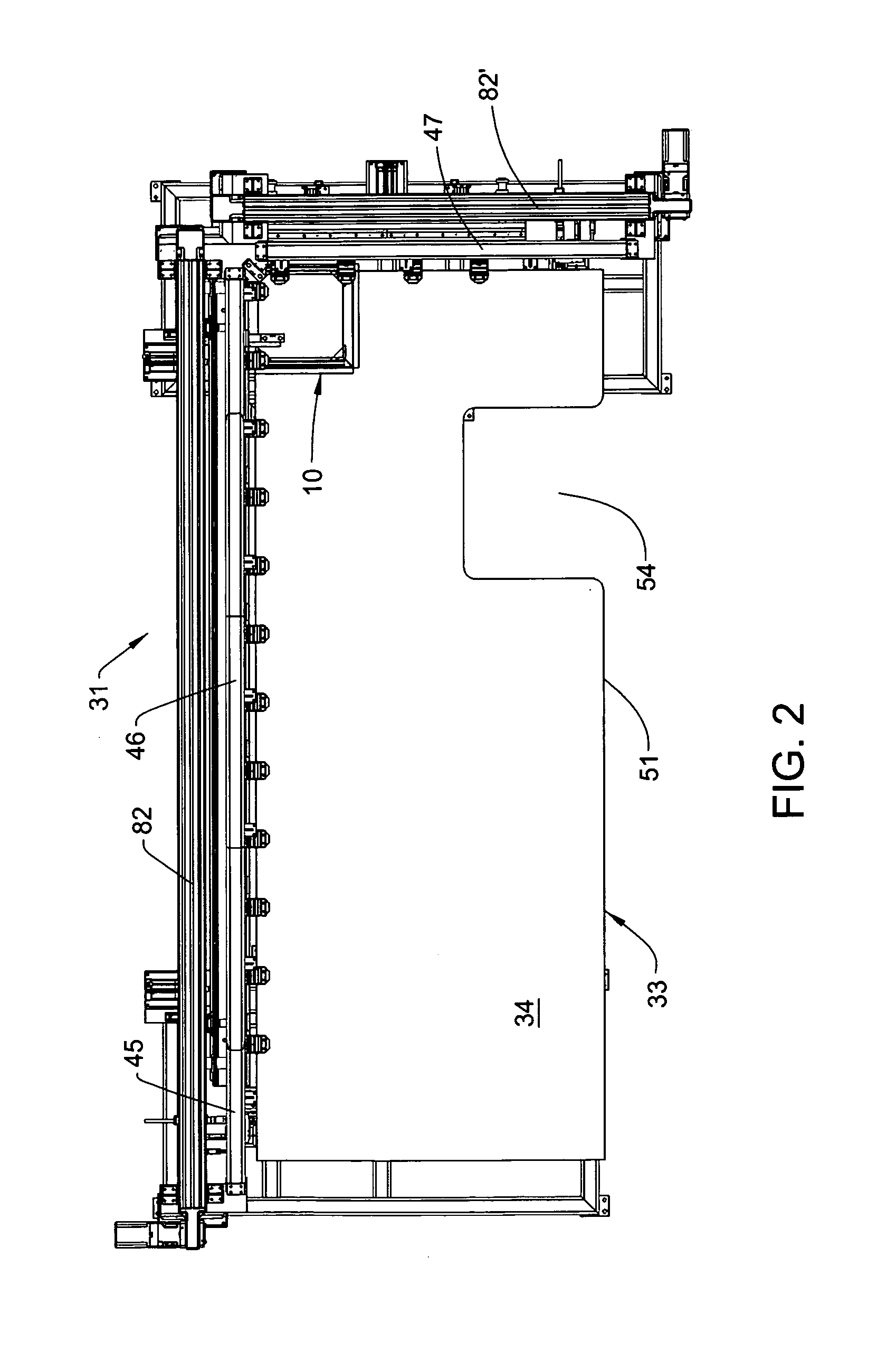
A process and apparatus for wrapping an edge flap of a panel-shaped workpiece, wherein the workpiece has a flexible covering sheet extending over a front face thereof and having flexible edge flaps protruding outwardly beyond the respective edge faces. The workpiece is positioned on a support table so that the flexible cover sheet faces downwardly, and one edge of the workpiece and the respective protruding flap are disposed to overhang and protrude outwardly beyond the support table. The workpiece is initially disposed in proper location by temporary positioning elements, and clamps are downwardly extended to engage the workpiece and fix it to the table. Adhesive is applied to the back of the protruding edge flap. An edge wrapping arrangement disposed adjacent the edge of the table is provided with first and second wiping blades so that upward movement of the wiping arrangement causes the first wiping blade to engage the edge flap and wipe it upwardly into engagement with the edge face of the workpiece, following which the wiping arrangement moves the second blade horizontally inwardly over the workpiece so that the second blade engages the end part of the flap and wipes it downwardly into engagement with the upward-facing back face of the workpiece.

Description

FIELD OF THE INVENTION[0001]This invention relates to an apparatus and process for wrapping edge flaps of a thin flexible covering sheet around the edges of a substrate, such as a panel-shaped structure, for defining a cover pad or panel for an upright wall or similar structure.BACKGROUND OF THE INVENTION[0002]Wall systems defined by upright space-dividing panels are widely utilized in offices and the like to divide large open areas into smaller workspaces. Such panels, which may be of floor-to-ceiling height or of lesser height, are typically prefabricated and employ a rigid frame to which side cover pads are attached for enclosing the frame and defining the desired aesthetics of the finished wall panel. The cover pads, which may extend the full vertical height of the frame, or which may be a plurality of smaller pads which attach to the frame, typically include a sheet-like or plate-like substrate which is exteriorly covered by a thin flexible covering sheet to provide desired fun...

Claims


Application Information

Patent Timeline
IPC IPC(8): B32B38/00B29C65/52B32B38/18B32B3/04
CPCB29C63/04Y10T156/10Y10T156/1007Y10T156/1015Y10T156/1011Y10T156/101Y10T156/1008Y10T156/1002Y10T156/1034
Inventor BROWN, RONALD H.SNYDER, LARRY
Owner HAWORTH SPA
Why Eureka
Try Eureka