Elevator with a monitoring system

Active Publication Date: 2011-12-15
INVENTIO AG
View PDF11 Cites 12 Cited by
  • Summary
  • Abstract
  • Description
  • Claims
  • Application Information

AI Technical Summary

Benefits of technology

[0006]It is therefore an object of the present invention t

Problems solved by technology

A complicated and expensive cabling of the peripheral apparatus is redundant.
However, the periodic interrogation of the status of

Method used


Image

  • Elevator with a monitoring system
  • Elevator with a monitoring system
  • Elevator with a monitoring system

Examples


Example

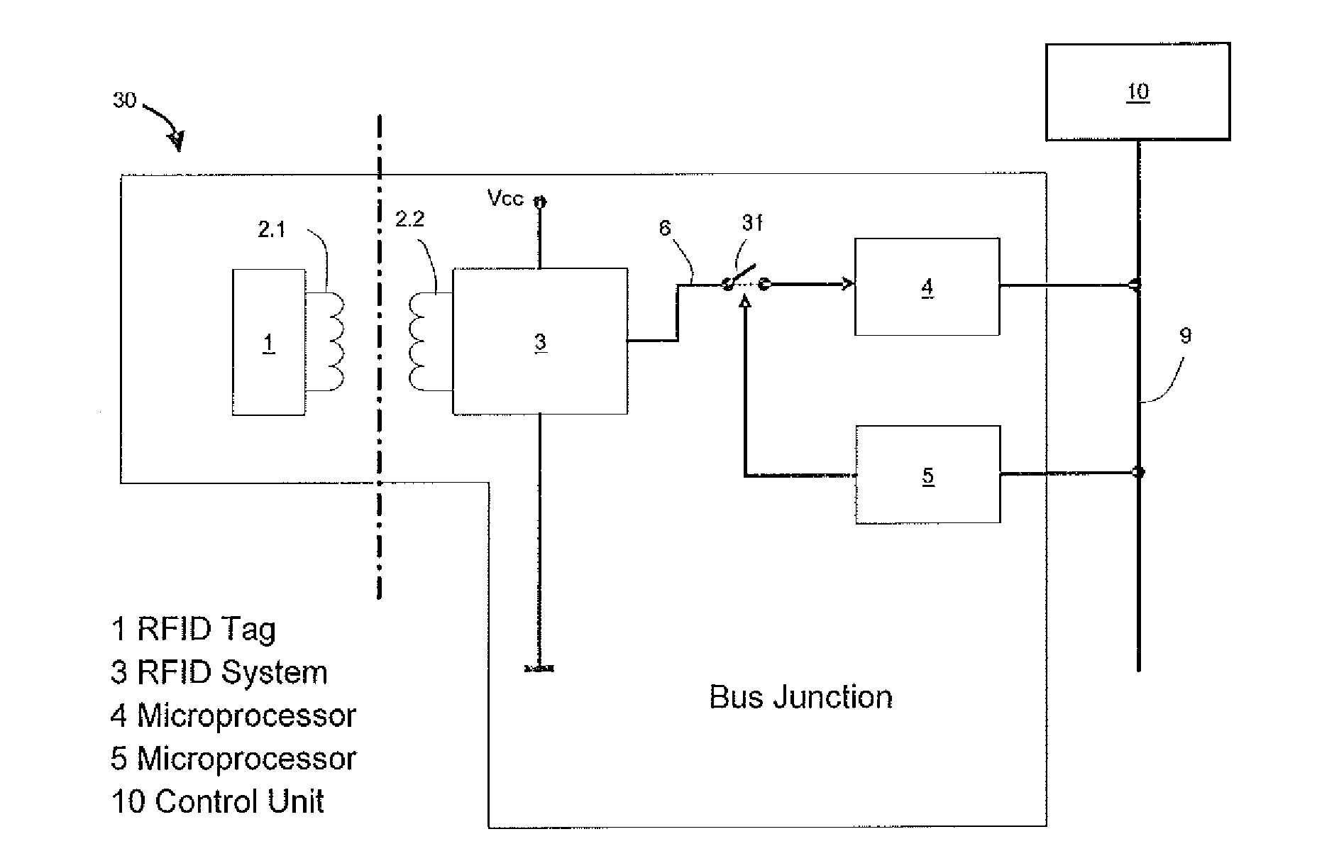
[0032]FIG. 1 shows a first exemplifying embodiment of the monitoring system as used, for example, in an elevator. A control unit 10 is connected with a bus 9. The control unit 10 communicates with at least one bus junction 30 by way of the bus 9. The control unit 10, the bus 9 and the at least one bus junction 30 form a bus system. Within this bus system each bus junction 30 has a uniquely identifiable address. Signals from the control unit 10 can be selectively communicated to a specific bus junction 30 by means of this address. Equally, incoming signals at the control unit 10 are uniquely assignable to a bus junction 30.

[0033]Data can thus be sent in both directions between the bus junction 30 and the control unit 10 by way of the bus 9. The bus junction 30 has for this purpose at least two microprocessors 4 and 5. The two microprocessors 4 and 5 are so designed that the first microprocessor 4 communicates at least status data to the control unit 10 and the second microprocessor 5...


PUM


Abstract

An elevator has a control unit, a bus, a first microprocessor and at least a second microprocessor, which microprocessors are associated with a bus junction and which are connected by the bus with the control unit. The control unit communicates an instruction by the bus to the second microprocessor to interrupt a signal transmission to the first microprocessor so that the first microprocessor transmits a status message to the control unit.

Description

FIELD OF THE INVENTION[0001]The invention relates to an elevator with a monitoring system for monitoring a status of associated microprocessors.BACKGROUND OF THE INVENTION[0002]WO 03 / 107295 A1 shows a monitoring system for status monitoring of peripheral apparatus, for example elevator components. For that purpose the bus system has a bus, a central control unit, which is connected with the bus, and several peripheral apparatus. Each of these apparatus lies at a bus junction and communicates with the control unit by means of the bus. At every point in time the peripheral apparatus adopt a specific status. The control unit periodically interrogates the states of each peripheral apparatus by way of the bus.[0003]The bus is supplied with energy by the control unit and supplies electromagnetic induction loops which are part of a bus junction. The individual peripheral apparatus are coupled to the induction loops of the bus junctions by way of a local antenna and draw electromagnetic ene...

Claims


Application Information

Patent Timeline
IPC IPC(8): G05B15/00
CPCB66B13/22
Inventor SONNENMOSER, ASTRIDMICHEL, DAVIDHESS, MARTIN
Owner INVENTIO AG
Why Eureka
Try Eureka