Eureka AIR delivers breakthrough ideas for toughest innovation challenges, trusted by R&D personnel around the world.

Injection molding method and injection molding machine

Active Publication Date: 2011-12-15
SUMITOMO HEAVY IND LTD
View PDF3 Cites 2 Cited by
  • Summary
  • Abstract
  • Description
  • Claims
  • Application Information

AI Technical Summary

Benefits of technology

[0013]According to an embodiment of the invention, there is provided an injection molding method of an injection molding machine including reducing a cross-section of a flow passage of a gas discharge portion formed at parting surfaces at a predetermined timing after a start of a filling of a molding material.

Problems solved by technology

However, the screw portion requires sufficiently high strength.
In particular, if sinks are formed on the surface of the screw portion of the preform or bubbles are formed in the screw portion, a sealing property between a cap and the screw portion of a finished container deteriorates.
For this reason, it is not possible to seal the container by the cap.

Method used


Image

  • Injection molding method and injection molding machine
  • Injection molding method and injection molding machine
  • Injection molding method and injection molding machine

Examples


Embodiment Construction

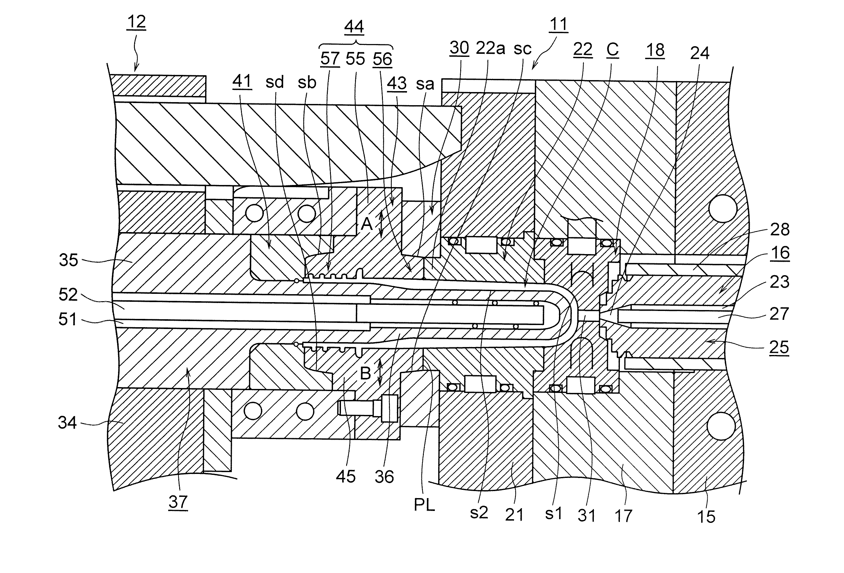
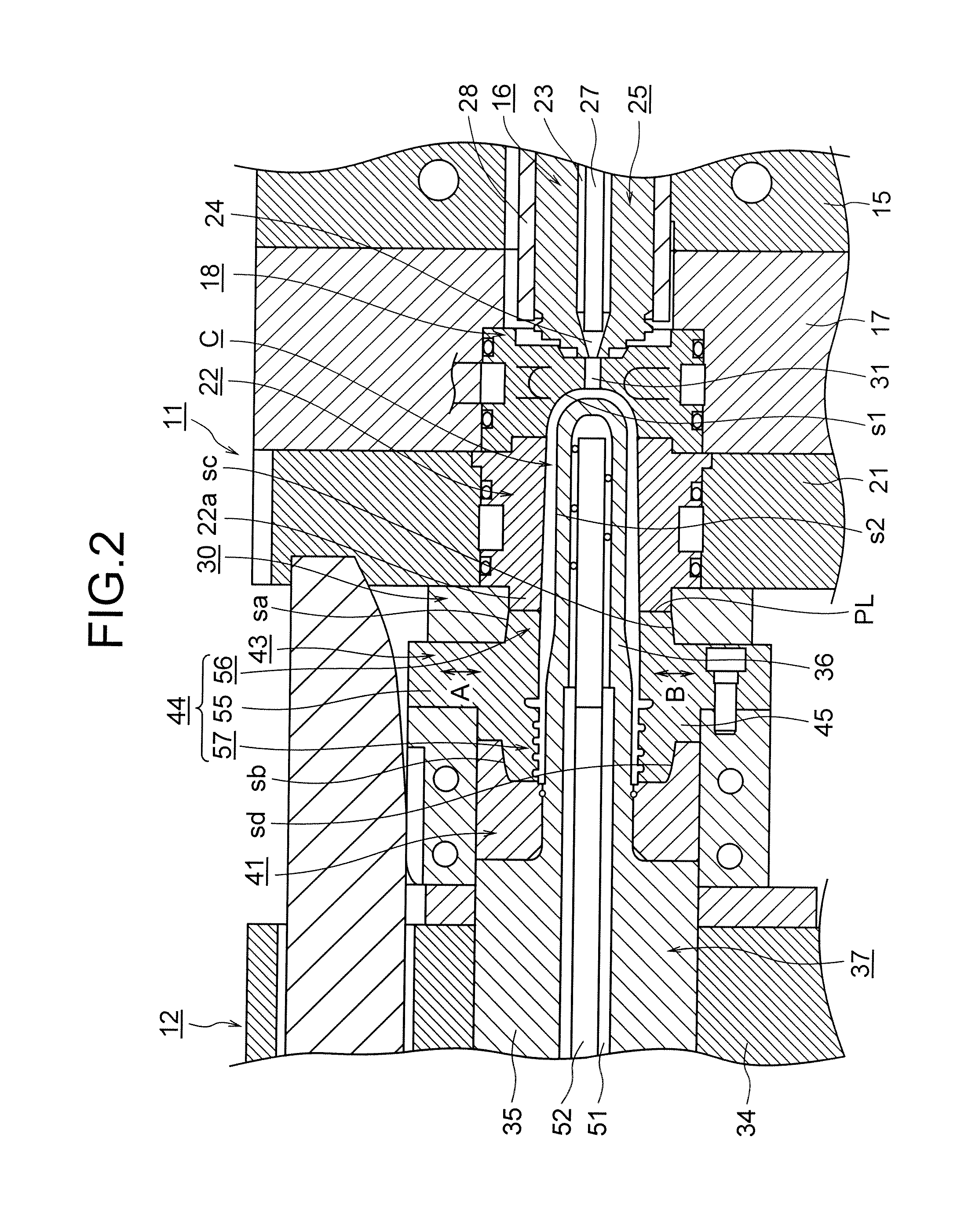
[0019]in the mold device in the related art, an ingredient contained in the gas, for example, an oligomer (low-molecular resin) adheres to the inner peripheral surface of the gas vent as a foreign material when the gas passes through the gas vent. For this reason, the gas vent is clogged in a short time. Accordingly, since the mold device needs to be cleaned at regular intervals and adhering oligomer needs to be removed, not only the maintenance of the mold device is troublesome but also the productivity of a preform deteriorates.

[0020]There is a need for providing an injection molding method that can suppress the clogging of a gas vent, simplify the maintenance of a mold device, and improve the productivity of a molded product.

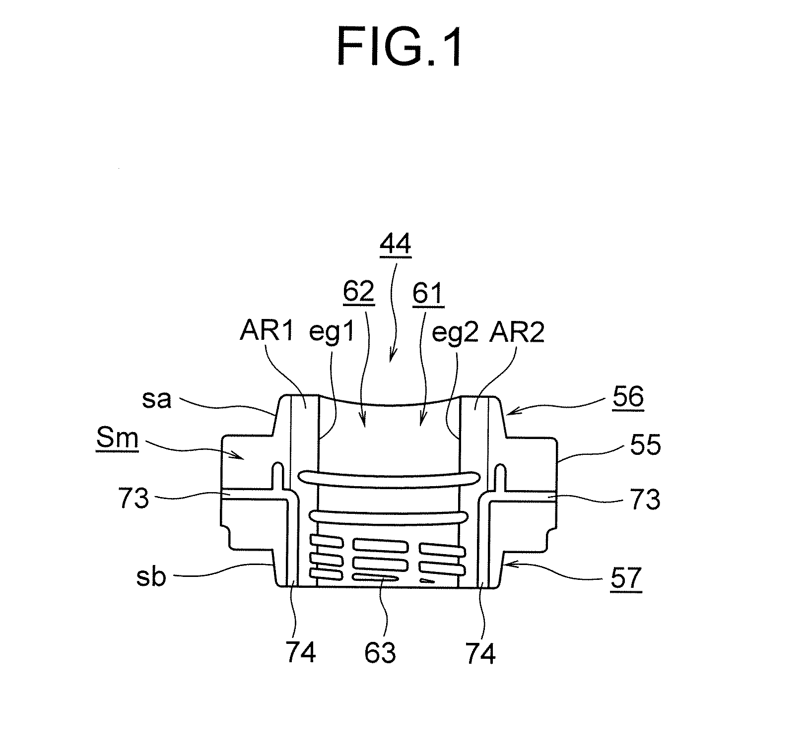
[0021]An injection molding method according to an embodiment of the invention is applied to an injection molding machine including a split mold where a gas discharge portion is formed at parting surfaces.

[0022]Further, the cross-section of a flow passage of t...


PUM

PropertyMeasurementUnit
Forceaaaaaaaaaa

Abstract

It may be possible to suppress the clogging of a gas vent, to simplify the maintenance of a mold device, and to improve the preform productivity.The invention may be applied to an injection molding machine including a split mold where a gas discharge portion is formed at parting surfaces. Further, the cross-section of a flow passage of the gas discharge portion is reduced at a predetermined timing after the start of the filling of a molding material. Since the cross-section of the flow passage of the gas discharge portion is reduced after a cavity space starts being filled with a molding material, it may be possible to make the amount of gas, which flows through the gas discharge portion, large until the cross-section of the flow passage of the gas discharge portion is reduced. It may be possible to prevent a foreign material from adhering to the inner peripheral surface of the gas discharge portion.

Description

RELATED APPLICATION[0001]This application is based upon and claims the benefit of priority from Japanese Patent Application No. 2010-136028, filed on Jun. 15, 2010, the entire contents of which are incorporated herein by reference.BACKGROUND[0002]1. Technical Field[0003]The present invention relates to an injection molding method and an injection molding machine.[0004]2. Description of Related Art[0005]In the past, in a stretch blow molding method that forms a container made of a resin, for example, a PET resin, a container has been formed as a finished product, that is, a finished molded product formed by forming a preform (a parison with a bottom) in advance as a preliminarily molded product, that is, a preliminary molding by an injection molding machine, setting the preform in a stretch blow molding machine, mechanically stretching the preform in an axial direction while the preform is heated and softened, and stretching the preform in a radial direction by air blowing.[0006]Mean...

Claims


Application Information

Patent Timeline
IPC IPC(8): B29C45/57B29C45/26
CPCB29C45/34B29K2105/253B29C45/7653B29C45/56
Inventor SAKAMOTO, ICHIRO
Owner SUMITOMO HEAVY IND LTD
Why Eureka
Eureka Blog
Learn More