Vehicle body front structure and manufacturing method thereof

Inactive Publication Date: 2011-12-15
HONDA MOTOR CO LTD
View PDF2 Cites 31 Cited by
  • Summary
  • Abstract
  • Description
  • Claims
  • Application Information

AI Technical Summary

Benefits of technology

[0037]In the method described above, the upper movement bracket is fastened to the upper support bracket by the top fastening means before the upper support bracket is attached to the upper beam of the front bulkhead. Therefore, it is possible to suitably adjust the fastening load when the upper movement bracket is fastened to the upper support bracket by the top fastening means. Similarly, the lower movement bracket is fastened to the lower support bracket by the bottom fastening means before the lower support bracket is attached to the lower beam of the front bulkhead. Therefore, it is possible to suitably adjust the fastening load when the lower movement bracket is fastened to the lower support bracket by the bottom fastening means.
[0038]Thus, by suitably adjusting the fastening load of the top and bottom fastening means, it is easy to manage the fastening load and a satisfactor

Problems solved by technology

Thus, when the upper beam and the lower support bracket are assembled as component units, adjusting the fastening load requires more labor than adjusting the fastening loads of bolts.
Therefore, labor is required for assembling the cooling sys

Method used


Image

  • Vehicle body front structure and manufacturing method thereof
  • Vehicle body front structure and manufacturing method thereof
  • Vehicle body front structure and manufacturing method thereof

Examples


Embodiment Construction

[0063]The front side frames, upper members, and upper side frames constituting the framework of a vehicle body front structure 10 according to the present embodiment are bilaterally symmetric; therefore, the left-side components are described and descriptions of the right-side components are omitted.

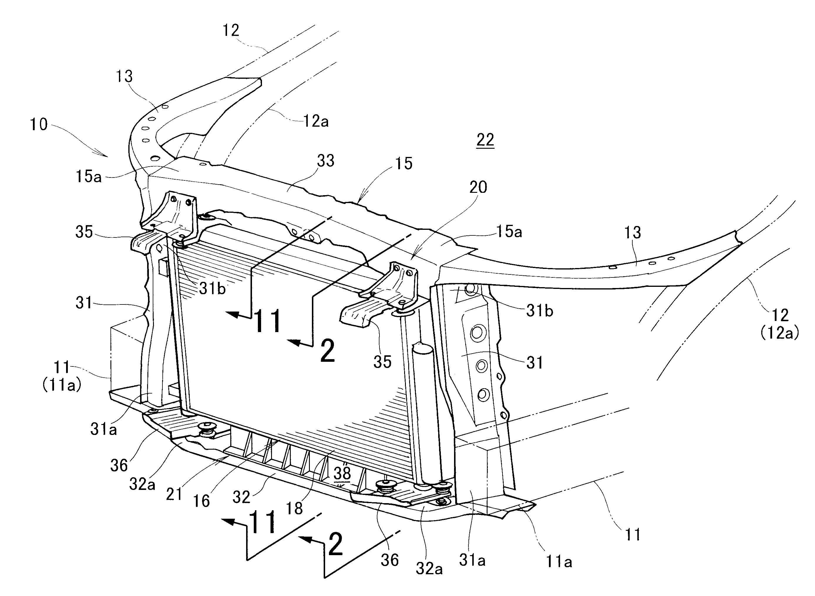
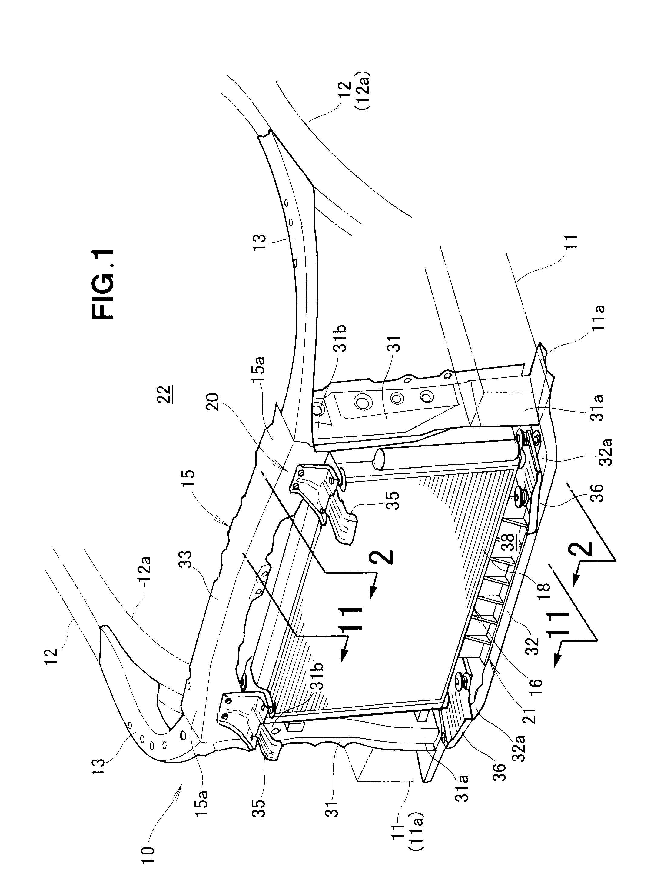
[0064]As shown in FIG. 1, the vehicle body front structure 10 comprises left and right front side frames 11 provided to the left and right sides of the front of the vehicle body, left and right upper members 12 provided above the outer sides of the left and right front side frames 11, left and right upper side frames 13 provided to the left and right upper members 12, a bulkhead 15 provided to the left and right upper side frames 13 and the left and right front side frames 11, a cooling system support unit 20 which is provided to the bulkhead 15 and which supports a cooling system component 16, and a wall member 21 provided within the cooling system support unit 20.

[0065]The cooling syst...


PUM

PropertyMeasurementUnit
Resilienceaaaaaaaaaa

Abstract

A vehicle body front structure is disclosed in which a cooling system component is provided to an upper beam and a lower beam of a front bulkhead. A vehicle body front structure comprises a left top support mechanism provided to the upper beam and a left bottom support mechanism provided to the upper beam. The left top support mechanism supports a left top part of the cooling system component, and supports the left top part of the cooling system component so as to allow the left top part to move toward the rear of the vehicle body. The left bottom support mechanism supports a left bottom part of the cooling system component, and supports the left bottom part of the cooling system component so as to allow the left bottom part to move toward the rear of the vehicle body.

Description

FIELD OF THE INVENTION[0001]The present invention relates to a vehicle body front structure in which a cooling system component is provided to an upper beam and a lower beam of a front bulkhead.BACKGROUND OF THE INVENTION[0002]Among vehicle body front structures, there are those having a structure in which a front bulkhead is provided to left and right front side frames and left and right upper members, and a cooling system component is provided to the front bulkhead.[0003]The top part of the cooling system component is attached to an upper beam of the front bulkhead, and the bottom part of the cooling system component is attached to a lower beam of the front bulkhead via a lower support bracket.[0004]The upper beam is fastened to left and right upper members by bolts so as to be capable of moving toward the rear of the vehicle body. The lower support bracket is fastened to the lower beam by bolts so as to be capable of moving toward the rear of the vehicle body.[0005]According to t...

Claims


Application Information

Patent Timeline
IPC IPC(8): B62D25/08B21D53/02
CPCB60K11/04Y10T29/4935B62D25/084B60Y2306/01
Inventor KIHARA, MAKOTOTAKEDA, TOMOYAYANAOKA, TOSHIYUKIKASHIWAGI, MASAKAZU
Owner HONDA MOTOR CO LTD
Why Eureka
Try Eureka