Optical device for stereoscopic display and stereoscopic display apparatus

Inactive Publication Date: 2011-12-15
SONY CORP
View PDF4 Cites 14 Cited by
  • Summary
  • Abstract
  • Description
  • Claims
  • Application Information

AI Technical Summary

Benefits of technology

[0027]In the optical devices for stereoscopic display according to the first to third viewpoints of the invention or the stereoscopic display apparatuses according to the embodiment of the invention, the first transparent parallel plate is disposed to be in contact with the first surface of the display

Problems solved by technology

Since the panel includes thin glass sheets bonded to each other, thickness of the panel is approximately 0.6 to 2.4 mm e

Method used


Image

  • Optical device for stereoscopic display and stereoscopic display apparatus
  • Optical device for stereoscopic display and stereoscopic display apparatus
  • Optical device for stereoscopic display and stereoscopic display apparatus

Examples


Example

First Embodiment

[0049]General configuration of optical device for stereoscopic display 10

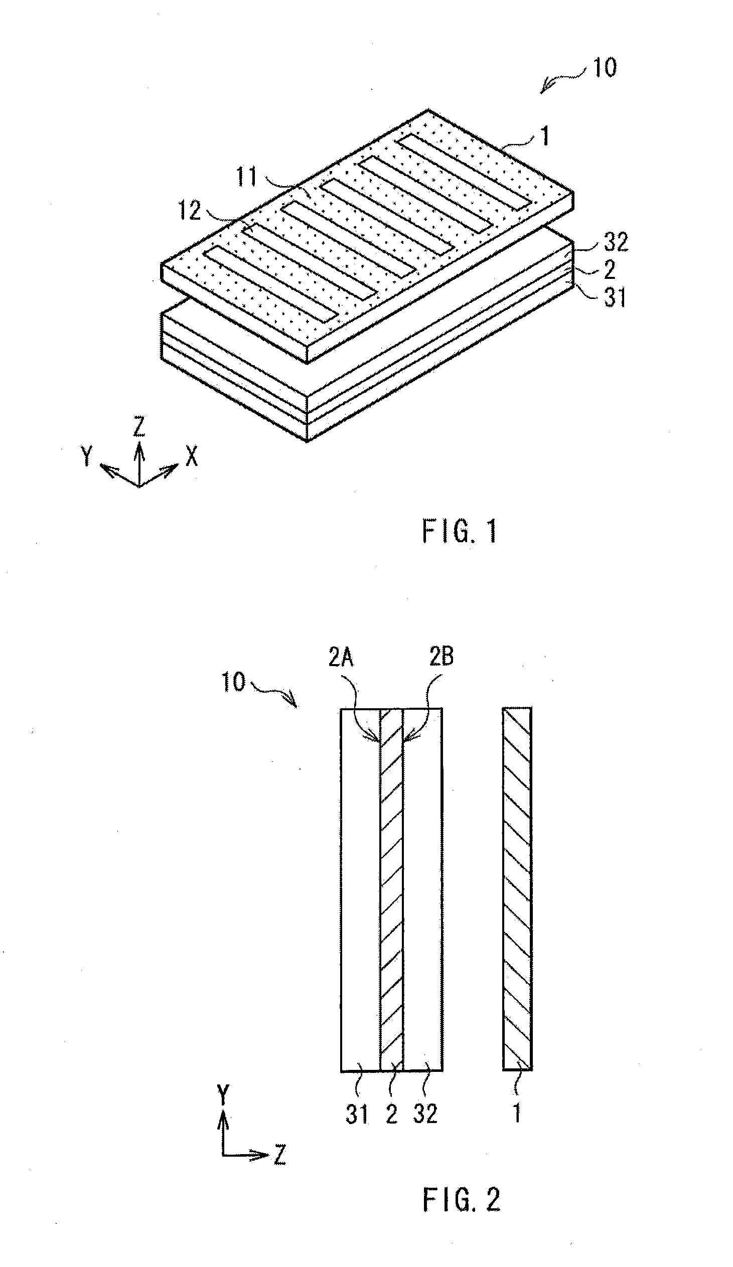
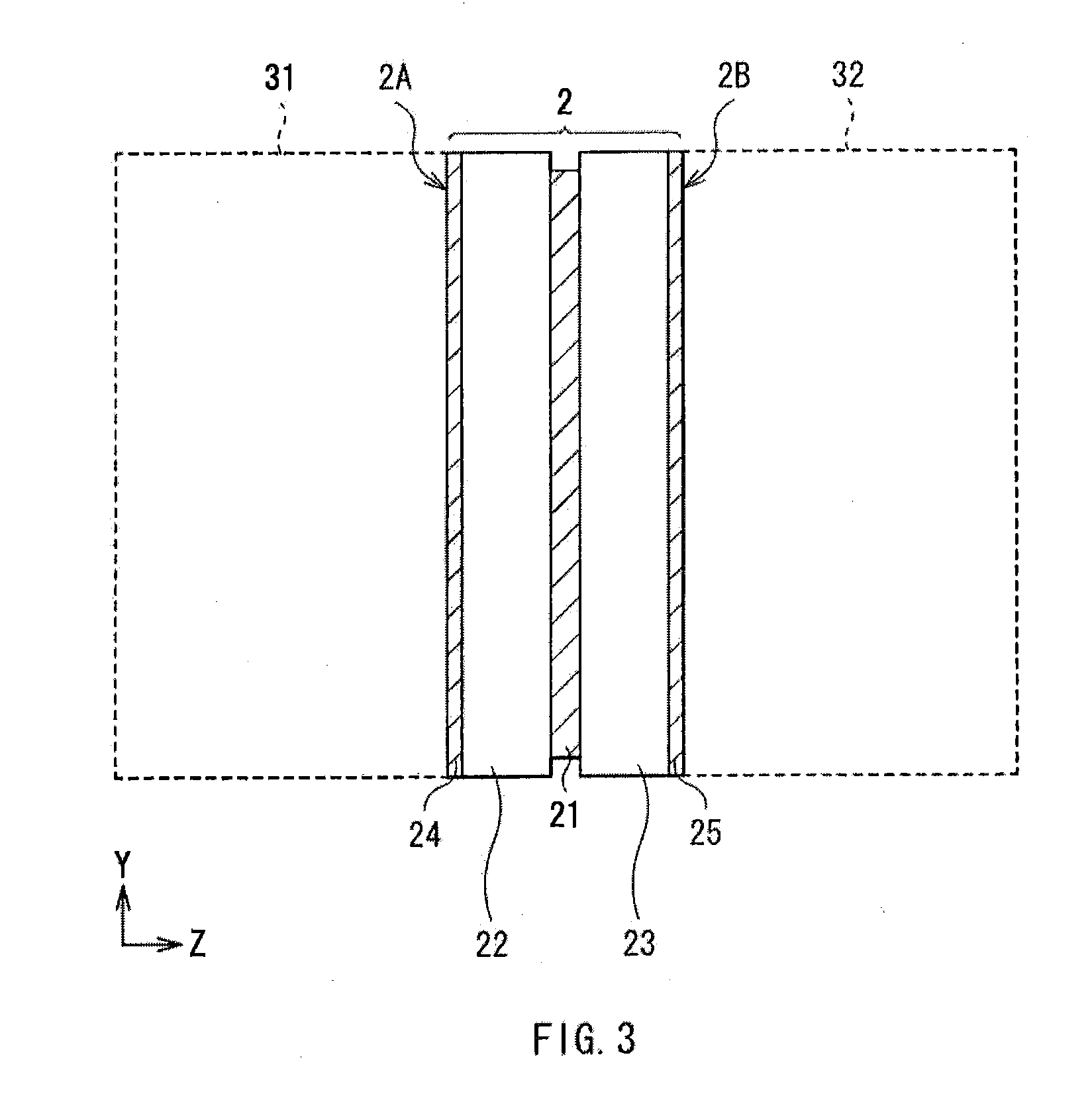
[0050]FIGS. 1 and 2 show a configuration example of an optical device for stereoscopic display 10 according to a first embodiment of the invention. The optical device for stereoscopic display 10 has a parallax barrier 1, a liquid crystal display panel 2, a first transparent parallel plate 31 and a second transparent parallel plate 32. The liquid crystal display panel 2, which corresponds to a display section for two-dimensional image display, has a first surface 2A and a second surface 2B opposed to each other. A second surface 2B side corresponds to a side (viewer side) for image display, from which displayed-image light is emitted. The parallax barrier 1, which is a parallax separation section for splitting displayed-image light from the liquid crystal display panel 2 so as to enable stereoscopy, is disposed to face the liquid crystal display panel 2 on a side of the second surface 2B.

[0051]A ...

Example

Second Embodiment

[0072]Next, an optical device for stereoscopic display according to a second embodiment of the invention is described. Substantially the same components as those of the optical device for stereoscopic display 10 according to the first embodiment are designated by the same symbols, and description of them is appropriately omitted. The optical device for stereoscopic display according to the second embodiment may be also applied to the stereoscopic display apparatus 40 shown in FIG. 4.

[0073]FIG. 5 shows a configuration example of an optical device for stereoscopic display according to the embodiment. The optical device for stereoscopic display has a light source 51, which emits light for image display to a liquid crystal display panel 2, on a back side (side opposite a first surface 2A) of the panel 2. The light source 51 is a light emitter such as CCFL (Cold Cathode Fluorescent Lamp) or LED (Light Emitting Diode).

[0074]Moreover, the optical device for stereoscopic di...

Example

Third Embodiment

[0078]Next, an optical device for stereoscopic display according to a third embodiment of the invention is described. Substantially the same components as those of the optical device for stereoscopic display 10 according to the first embodiment are designated by the same symbols, and description of them is appropriately omitted. The optical device for stereoscopic display according to the third embodiment may be also applied to the stereoscopic display apparatus 40 shown in FIG. 4.

[0079]FIG. 6 shows a configuration example of an optical device for stereoscopic display according to the embodiment. The optical device for stereoscopic display has a light source 51, which emits light for image display to a liquid crystal display panel 2, on a back side (side opposite a first surface 2A) of the panel 2. The light source 51 is a light emitter such as CCFL or LED.

[0080]Moreover, the optical device for stereoscopic display has a diffuser plate 53 between the light source 51 ...


PUM


Abstract

An optical device for stereoscopic display includes: a display section having a first surface and a second surface opposed to each other and outputting displayed-image light from the second surface; a parallax separation section disposed to face the second surface of the display section, and splitting the displayed-image light from the display section to allow stereoscopy; a first transparent parallel plate disposed to be in contact with the first surface of the display section; and a second transparent parallel plate disposed to be in contact with the second surface of the display section.

Description

BACKGROUND OF THE INVENTION[0001]1. Field of the Invention[0002]The present invention relates to an optical device for stereoscopic display and a stereoscopic display apparatus, enabling, for example, parallax-barrier-type stereoscopy.[0003]2. Description of Related Art[0004]A technique for stereoscopic display may be classified into two methods, a method with glasses used by a viewer, and a method enabling autostereoscopy without use of glasses by a viewer. The latter display method is called autostereoscopic display method. A typical autostereoscopic display method includes a parallax barrier type and a lenticular lens type. In the parallax barrier type or the lenticular lens type, parallax images (a right-eye image and a left-eye image in the case of two viewpoints) for stereoscopy are displayed on a two-dimensional display panel in a spatially divided manner, and parallax separation of the parallax images is performed in a horizontal direction by a parallax separation section so...

Claims


Application Information

Patent Timeline
IPC IPC(8): H04N13/04G02F1/1335G02B27/26G02B27/22G02B30/25G02B30/30G02B30/31
CPCG02B27/26G02B27/2214G02B30/25G02B30/31G02B30/30G02F1/13G02F1/1335G02B30/00G02B30/27
Inventor SATO, YOSHIHISAMORITA, MASAYOSHINAGAI, HIROYUKIOKAMOTO, YOSHIKI
Owner SONY CORP
Why Eureka
Try Eureka