Method of controlling a lighting system

a lighting system and control command technology, applied in the field of lighting system control, can solve the problems of different delays in the reception of different control commands for different light source nodes, different delays, and unpleasant visual impression of the state-shift, such as wake-up or switch off lights, and achieve the effect of improving the visual effect of the state-shi

Inactive Publication Date: 2011-12-15
SIGNIFY HLDG BV
View PDF12 Cites 42 Cited by
  • Summary
  • Abstract
  • Description
  • Claims
  • Application Information

AI Technical Summary

Benefits of technology

[0023]Moreover, the state-shift command may include information as to controlling at least one of beam width, color, beam direction, dimming and intensity of the light source. In this way, the visual effect of the light sources may be adjusted and further synchronized depending on the type of light source. Other examples of state-shifts may be based on for example light curves, light waves, or light shapes.
[0024]Furthermore, at least the set of operating nodes located within the predetermined operating area may be adapted to take into account the state-shift delay when execu

Problems solved by technology

However, in large-scale wireless lighting systems not all light source nodes may be in communication range with the lighting system controller.
Rather, large-scale lighting systems require state-shift commands from the controller to the light source nodes to be routed also between the different light source nodes, effectively introducing different control command reception

Method used


Image

  • Method of controlling a lighting system
  • Method of controlling a lighting system
  • Method of controlling a lighting system

Examples


Embodiment Construction

[0032]The present invention will now be described more fully hereinafter with reference to the accompanying drawings, in which currently preferred embodiments of the invention are shown. This invention may, however, be embodied in many different forms and should not be construed as limited to the embodiments set forth herein; rather, these embodiments are provided for thoroughness and completeness, and fully convey the scope of the invention to those skilled in the art. Like reference characters refer to like elements throughout.

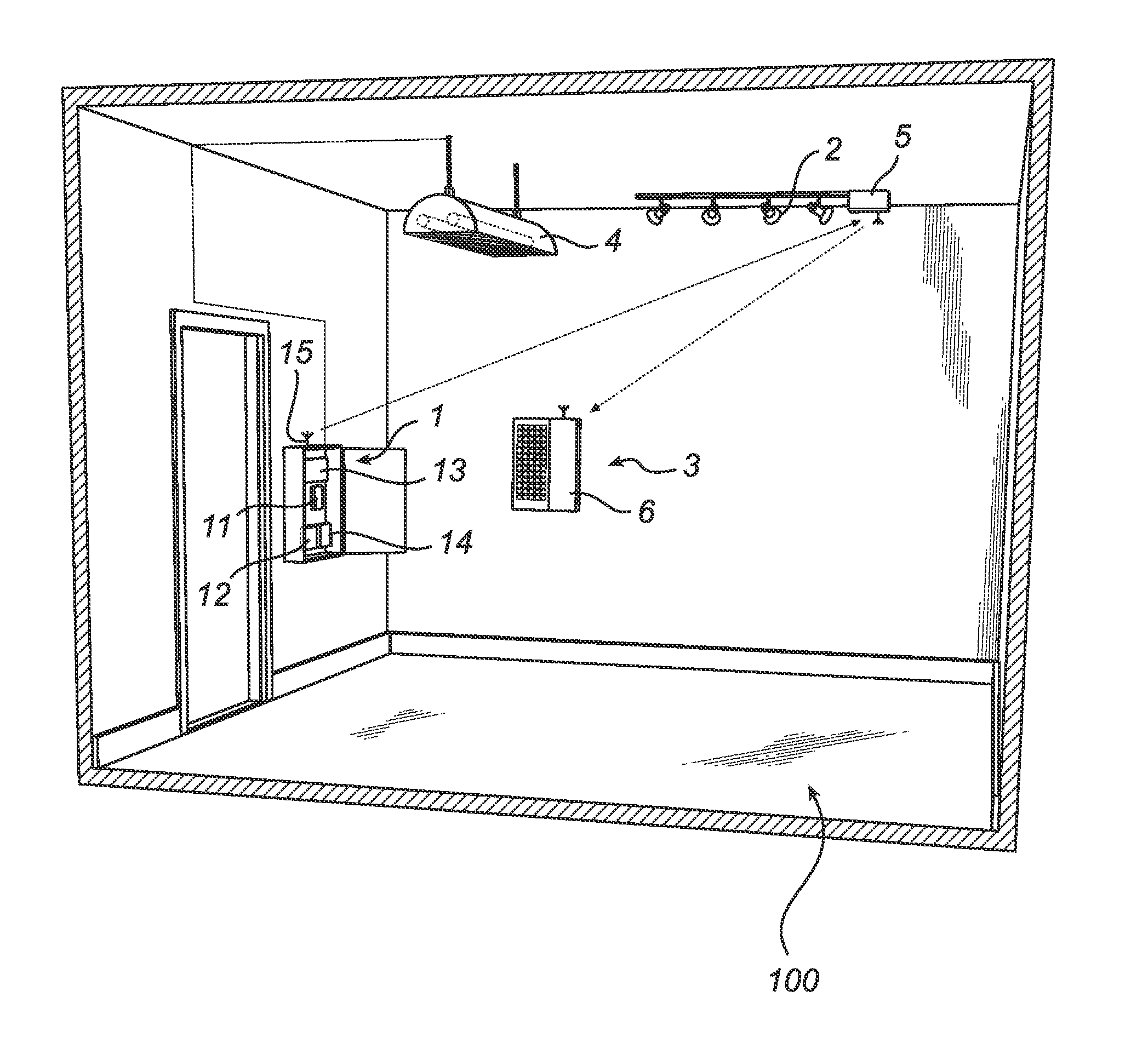
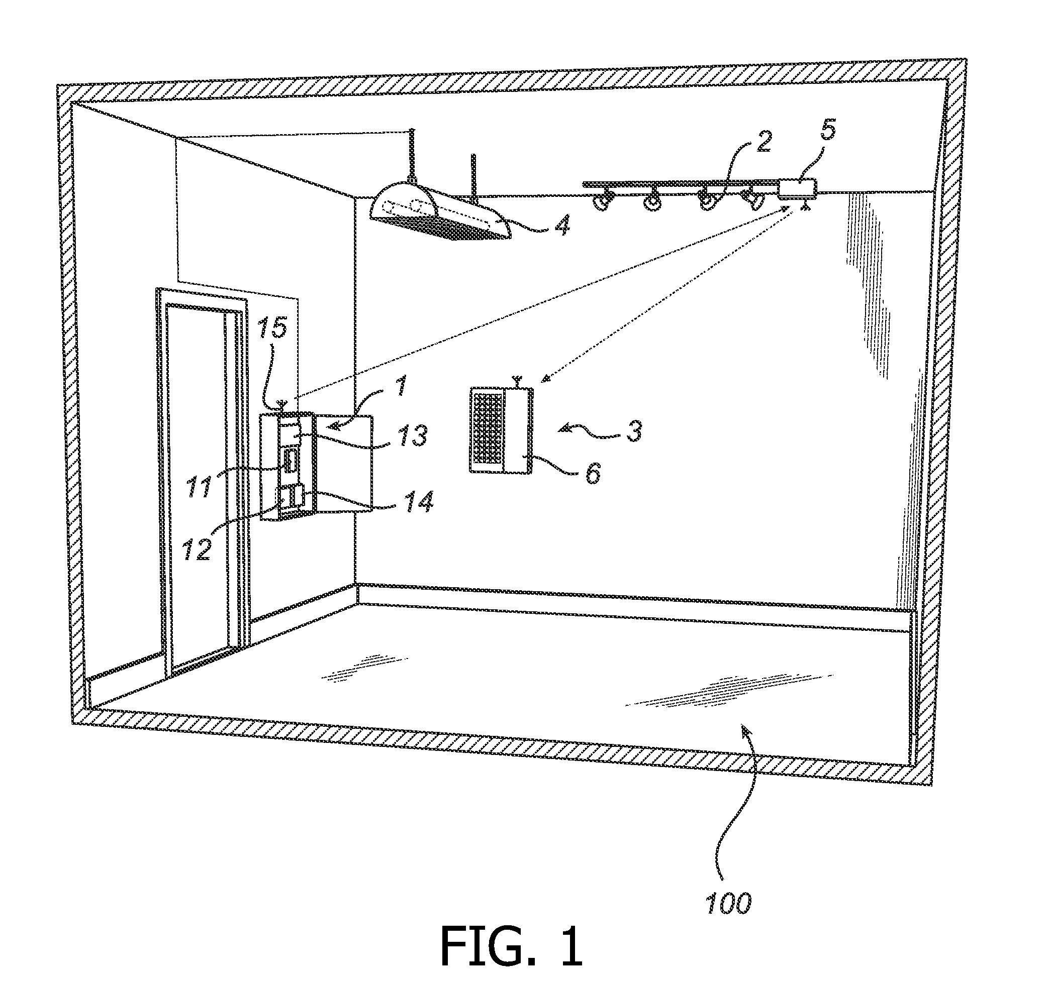
[0033]Referring now to the drawings and to FIG. 1 in particular, a lighting system 100 is depicted illustrating an exemplifying system in which the method of the present invention may be performed. The lighting system 100 comprises a controller 1 and a plurality of light source nodes 2, 3, 4 coupled together to form a network. For simplicity of explanation, there are only one controller 1 and three operating nodes 2, 3, 4, in the lighting system 100. Here, t...


PUM


Abstract

The present invention relates to a method of controlling a lighting system, the lighting system being arranged as a wireless network comprising a controller and a plurality of operating nodes arranged to communicate with each other, wherein the method comprises the steps of synchronizing the operating nodes with the controller, determining, from the plurality of operating nodes, a set of operating nodes that are located within a predetermined operating area, estimating a state-shift delay based on a maximum communication delay between the controller and the set of operating nodes located within the predetermined operating area, communicating the estimated state-shift delay to the plurality of operating nodes, and communicating a state-shift command to the plurality of operating nodes.
An advantage with the invention is that the visual artifact of the state-shift may be essentially removed as the time synchronization and timer interrupt alignment together with the estimated state-shift delay allows for the plurality of nodes to shift state at essentially the same time.

Description

TECHNICAL FIELD[0001]The present invention relates to a method of controlling a lighting system. The invention also relates to a lighting system adapted for performing such a method.BACKGROUND OF THE INVENTION[0002]Wireless control of lighting systems is increasingly replacing wired control, for example reducing installation costs and commissioning effort. A number of wireless technologies have been developed, including for example IEEE-802.15.4, Low-Power WiFi, WiFi, Bluetooth, EnOcean, Z-Wave and similar technologies, which typically permit short range communication.[0003]For real-time control of a wireless lighting system, it is desired to minimize the latency when switching a state of the light source nodes of the lighting system. An example of such a lighting system is disclosed in US2006 / 0154598, where a group of light source nodes of a radio network are arranged to selectively respond to broadcast messages from a lighting system controller, thereby providing decreased latency...

Claims


Application Information

Patent Timeline
IPC IPC(8): H04W4/00
CPCH05B37/0245Y02B20/42H05B37/0281H05B47/16H05B47/175Y02B20/40
Inventor SCHOOFS, ANTHONY ROBERT ANDREFUHRMANN, PETERAOUN, MARC
Owner SIGNIFY HLDG BV
Why Eureka
Try Eureka