Image processing method, and image processing device

a technology of image processing and processing method, applied in the field of image processing method and image processing device, can solve the problems of reducing the visibility of captured images, glare spots (bright spots) within captured images, loss of details, etc., and achieve the effect of reducing the effect of specular reflection

Inactive Publication Date: 2011-12-15
PANASONIC CORP
View PDF5 Cites 64 Cited by
  • Summary
  • Abstract
  • Description
  • Claims
  • Application Information

AI Technical Summary

Benefits of technology

[0031]According to the present invention, the influence of a saturated region with saturated pixel values, such as the effect of specular reflections, can be efficiently reduced.

Problems solved by technology

In various imaging applications, an effect called specular reflection may cause the occurrence of glare spots (bright spots) within a captured image.
Such bright spots mask the structure of the captured scene, resulting in loss of details and thus in a reduction of the visibility of such a captured image.
In particular, glossy materials, which reflect light to a large extent, such as wet surfaces may, when captured, lead to the origination of glare spots.
Especially in cases with a point-like light source, intense beams of light falling on the glossy surface may be reflected in the same direction, causing extremely bright spots in the image captured in such circumstances.
There are many examples where the specular reflection deteriorates the quality of the captured images.
An unpleasant consequence of the specular reflection is the loss of information occluded by the bright spots.
Such loss of information may be annoying for the persons viewing such a captured image.
Moreover, specular reflections may cause serious problems in applications such as document photographing.
In particular, the text or pictures of the photographed document may be occluded by the specular reflections, causing the photographed document to be incomplete.
Another field where specular reflections may lead to serious problems is medical imaging.
The images captured via endoscopy are particularly susceptible to specular reflections.
The bright spots resulting from specular reflections during the endoscopy significantly degrade the image quality.
In particular, in the over-saturated bright spot areas, there is no image information and consequently abnormalities could be missed by the physician during examination of the captured images.
Secondly, the endoscope is typically in a relative movement with respect to the captured object.
The moving bright spots on a display of an endoscopy device disturbs the physician in his diagnosis and surgery, and may distract his attention in particular in case of operations performed under use of endoscopy.

Method used


Image

  • Image processing method, and image processing device
  • Image processing method, and image processing device
  • Image processing method, and image processing device

Examples


embodiment 1

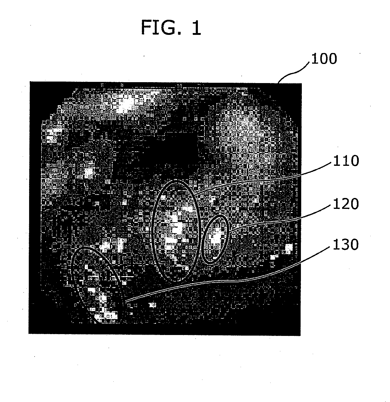
[0059]FIG. 1 shows an example of an image 100 captured using an endoscopy device (an endoscope). As can be seen in the image 100, specular reflections form rather small saturated image regions such as, regions in the area 110, 120 and 130. Consequently, there is no useful information in the positions of the specular reflections.

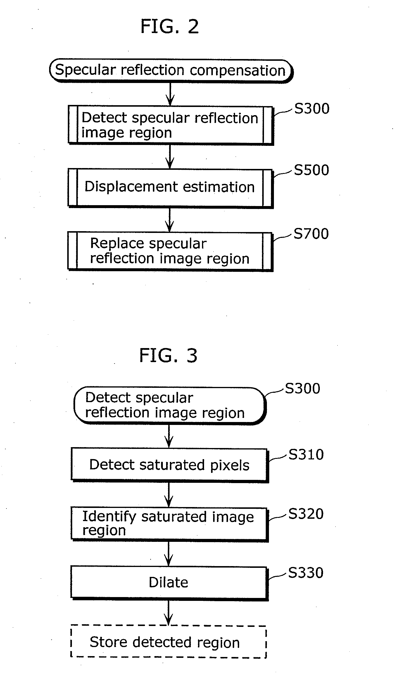
[0060]FIG. 2 is a flow diagram describing a method of detecting and reducing the specular reflections in a captured video sequence according to the present invention. The specular reflection reduction method of the present invention first detects a specular reflection region in the captured image (S300). In the next S500, another image or a plurality of images is searched for the regions corresponding to image regions covered by the specular reflection in the captured image. Finally, the specular reflection region in the captured image is replaced with the information from the one or a plurality of images (S700). Here, the image to be searched is an image in ...

embodiment 2

[0120]While a specular reflection region is to be replaced in Embodiment 1, a saturated region that is an image region with saturated pixel values and a false color region around the saturated region are to be replaced in Embodiment 2. The false color region is a region in which a blue false color appears around the saturated region with the saturated pixel values.

[0121]Although the following description mainly focuses on the differences with Embodiment 1, the description of the same processes as those in Embodiment 1 will be appropriately omitted.

[0122]The image to be processed in Embodiment 2 is a color image including RGB components, YUV components, or YCbCr components.

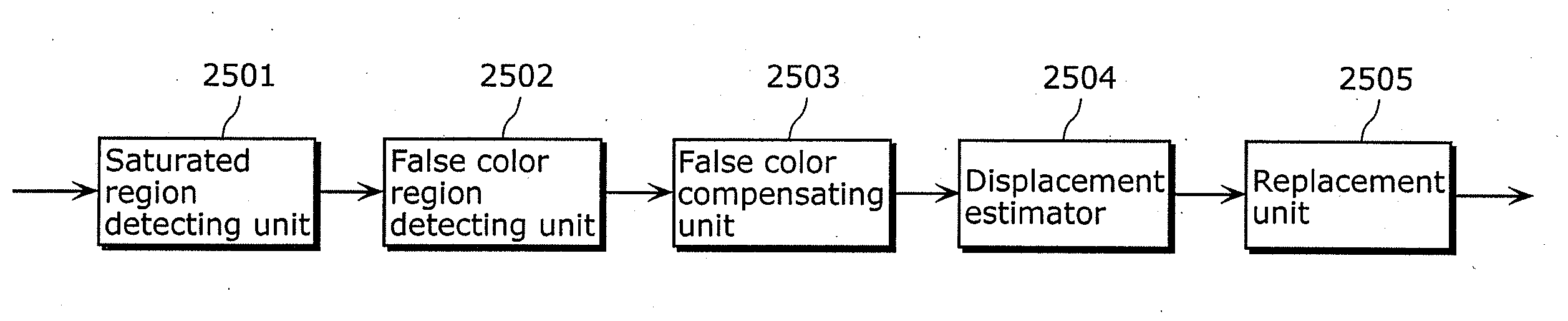
[0123]FIG. 13 is a block diagram illustrating a configuration of an image processing device according to Embodiment 2 in the present invention.

[0124]The image processing device according to Embodiment 2 includes a saturated region detecting unit 2501, a false color region detecting unit 2502, a false color compensa...

embodiment 3

[0152]According to Embodiment 2, a false color region is interpolated using a pixel value in the same image. In contrast, a false color region is interpolated using a pixel value in another image according to Embodiment 3.

[0153]Although the following description mainly focuses on the differences with Embodiments 1 and 2, the description of the same processes as those in Embodiments 1 and 2 will be appropriately omitted.

[0154]The image to be processed in Embodiment 3 is a color image including RGB components, YUV components, or YCbCr components.

[0155]FIG. 22 is a block diagram illustrating a configuration of an image processing device according to Embodiment 3 in the present invention.

[0156]The image processing device according to Embodiment 3 includes a saturated region detecting unit 2601, a false color region detecting unit 2602, a displacement estimator 2603, and a replacement unit 2604.

[0157]The saturated region detecting unit 2601 detects a pixel region (saturated region) with ...


PUM


Abstract

The image processing device includes: a specular reflection detector (1110) configured to detect, in a first image, an enlarged region including a saturated region and an adjacent region, the saturated region being a pixel region having a pixel value equal to or larger than a predetermined threshold, and the adjacent region at least partially surrounding the saturated region; and a replacement unit (1130) configured to replace a pixel value of a pixel included at least in the adjacent region, with one of (i) a pixel value of a pixel in a region of a second image that is located at a position corresponding to a position of the enlarged region in the first image and (ii) a pixel value of a pixel adjacent to the pixel in the second image, the adjacent region being included in the enlarged region detected by the specular reflection detector (1110).

Description

TECHNICAL FIELD[0001]The present invention relates to an image processing method and an image processing device for compensating a region with saturated pixel values and a region with a false color.BACKGROUND ART[0002]In various imaging applications, an effect called specular reflection may cause the occurrence of glare spots (bright spots) within a captured image. Such bright spots mask the structure of the captured scene, resulting in loss of details and thus in a reduction of the visibility of such a captured image.[0003]Assuming the bright spots in the captured image as pixel values, the values are saturated. For example, when each of pixels in a gray-scale image is represented by 8 bits, the pixel values can range from 0 to 255. Here, the bright spots are represented by 255 or a value closer to 255.[0004]During the process of imaging, a sensor captures light reflected from the scene to be captured. In general, the term “light” does not necessarily refer to the light in the visi...

Claims


Application Information

Patent Timeline
Patent Type & Authority Applications(United States)
IPC IPC(8): G06K9/46
CPCG06T5/005G06T2207/10068G06T5/50
Inventor WEDI, THOMASKNICKER, FLORIANPALFNER, TORSTENWITTMANN, STEFFEN
Owner PANASONIC CORP
Why Eureka
Try Eureka