Supercharge Your Innovation With Domain-Expert AI Agents!

Wire seal for metering of turbine blade cooling fluids

a cooling fluid and turbine blade technology, applied in the direction of liquid fuel engine components, non-positive displacement fluid engines, pump components, etc., can solve the problems of negative effect on the efficiency of the turbine engine, achieve the effect of effective metering of cooling fluid flow, improve overall engine performance, and reduce leakage flow

Active Publication Date: 2011-12-15
SIEMENS ENERGY INC
View PDF3 Cites 5 Cited by
  • Summary
  • Abstract
  • Description
  • Claims
  • Application Information

AI Technical Summary

Benefits of technology

"This patent is about a cooling system for turbine blades in a gas turbine engine. The system uses a teardrop shaped seal to seal the gap between the rotor and the sealing plate. The seal is forced radially outward and into the gap during operation, effectively metering the cooling fluid flow and reducing leakage. This improves engine performance without reducing component durability. The system also includes a cooling channel positioned between the root of the turbine blade and the offset rotor sealing plate for supplying cooling fluids to the blades."

Problems solved by technology

Turbine blades, vanes and other components often contain cooling systems for prolonging the life of these items and reducing the likelihood of failure as a result of excessive temperatures.
Often times, the cooling channels include leakage points at which leak cooling fluids from the cooling fluid channels, which negatively effects the efficiency of the turbine engine.

Method used


Image

  • Wire seal for metering of turbine blade cooling fluids
  • Wire seal for metering of turbine blade cooling fluids
  • Wire seal for metering of turbine blade cooling fluids

Examples


Embodiment Construction

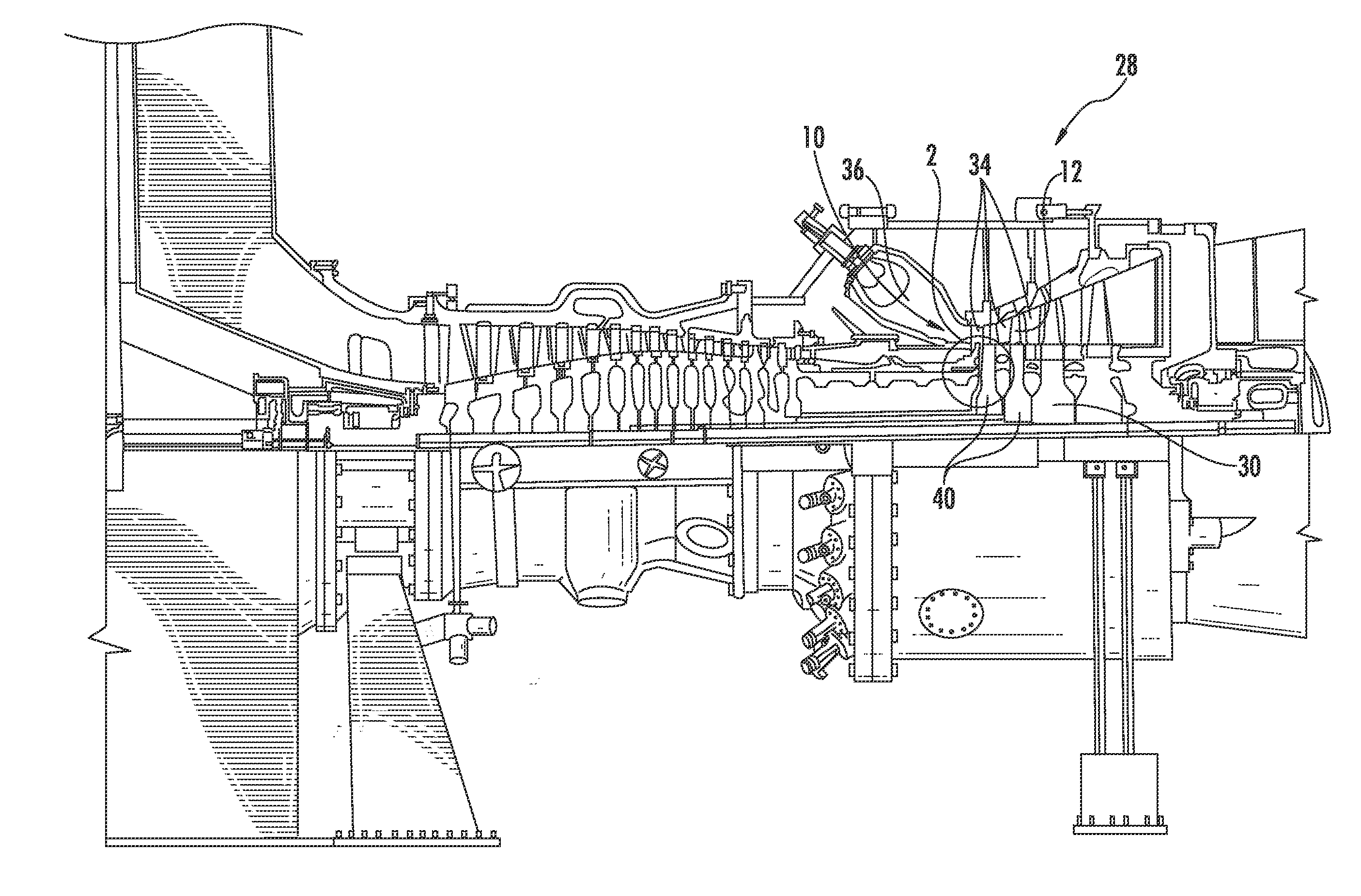
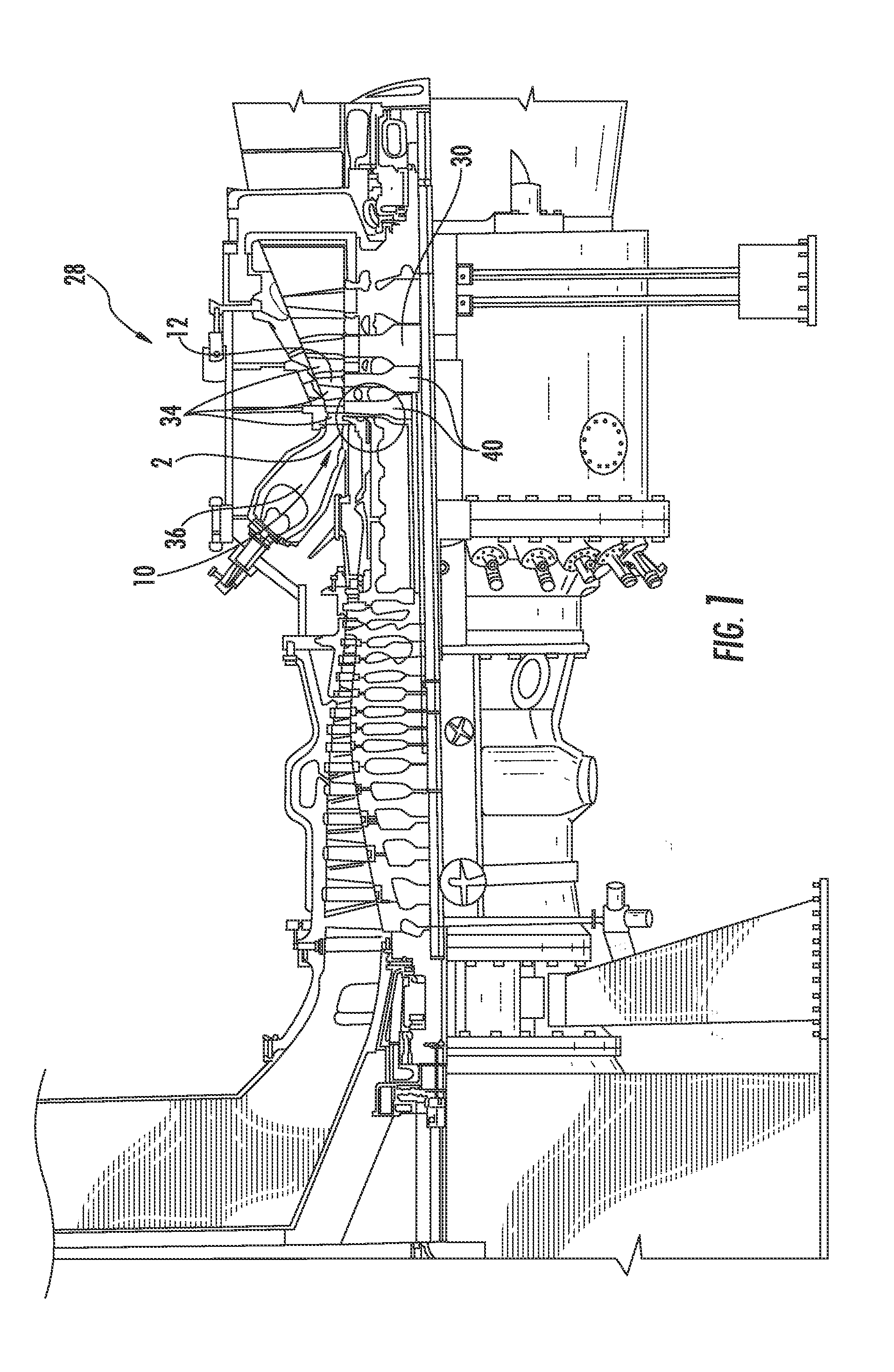
[0016]As shown in FIGS. 1-3, this invention is directed to a cooling fluid metering system 10 for a turbine blade 12 of a gas turbine engine 28. The cooling fluid metering system 10 may include a cooling channel 14 positioned between a root 16 of a turbine blade 12 and an offset rotor sealing plate 20 for supplying cooling fluids to turbine blades 12. At one point, a portion of the cooling channel 14 may include a gap 22 between the root 16 and the offset rotor sealing plate 20. The gap 22 may be sealed with teardrop shaped seal 24 positioned within a teardrop shaped cavity 26 at the gap 22. The cavity 26 and seal 24 may be positioned such that during operation, the seal 24 is forced radially outward and into the gap 22, thereby effectively metering cooling fluid flow, which may be, but is not limited to, cooling air, through the cooling channel 14. By metering the cooling fluid flow through the cooling channel 14, the amount of leakage flow can be reduced, thereby improving the ove...


PUM


Abstract

A cooling fluid metering system for a turbine blade of a gas turbine engine is disclosed. The cooling fluid metering system may include a cooling channel positioned between a root of a turbine blade and an offset rotor sealing plate for supplying cooling fluids to turbine blades. At one point, a portion of the cooling channel may include a gap between the root and the offset rotor sealing plate. The gap may be sealed with teardrop shaped seal positioned within a teardrop shaped cavity at the gap. The cavity and seal may be positioned such that during operation, the seal is forced radially outward and into the gap, thereby effectively metering cooling fluid flow through the cooling channel.

Description

CROSS-REFERENCE TO RELATED APPLICATION[0001]This application claims priority to U.S. Provisional Patent Application No. 61 / 353,730, filed Jun. 11, 2010, the entirety of which is incorporated herein.FIELD OF THE INVENTION[0002]This invention is directed generally to turbine engines, and more particularly to cooling fluid feed systems in turbine engines.BACKGROUND[0003]Typically, gas turbine engines include a compressor for compressing air, a combustor for mixing the compressed air with fuel and igniting the mixture, and a turbine blade assembly for producing power. Combustors often operate at high temperatures that may exceed 2,500 degrees Fahrenheit. Typical turbine combustor configurations expose turbine blade assemblies to these high temperatures. As a result, turbine blades and turbine vanes must be made of materials capable of withstanding such high temperatures. Turbine blades, vanes and other components often contain cooling systems for prolonging the life of these items and r...

Claims


Application Information

Patent Timeline
Patent Type & Authority Applications(United States)
IPC IPC(8): F01D5/08
CPCF01D11/006F01D5/081
Inventor AFANASIEV, GENNADIYBRILLERT, DIETER
Owner SIEMENS ENERGY INC
Features
  • R&D
  • Intellectual Property
  • Life Sciences
  • Materials
  • Tech Scout
  • Unparalleled Data Quality
  • Higher Quality Content
  • 60% Fewer Hallucinations
Learn More