Abutment for a dental implant

Inactive Publication Date: 2011-12-15
IVOCLAR VIVADENT AG
View PDF6 Cites 6 Cited by
  • Summary
  • Abstract
  • Description
  • Claims
  • Application Information

AI Technical Summary

Benefits of technology

[0009]The object of the present invention is therefore to make available an abutment which can be connected to a corresponding dental implant in a manner secure against rotation and which

Problems solved by technology

A problem that often arises in multi-part dental implant systems of this kind concerns the correct positioning of the abutment in the dental implant.
However, mainly because of the relatively large number of individual parts, the solution described in said document has disadvantages as regards the sterility and stability of the connection between

Method used


Image

  • Abutment for a dental implant
  • Abutment for a dental implant
  • Abutment for a dental implant

Examples


Embodiment Construction

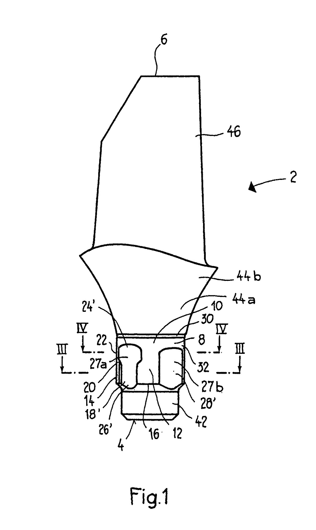
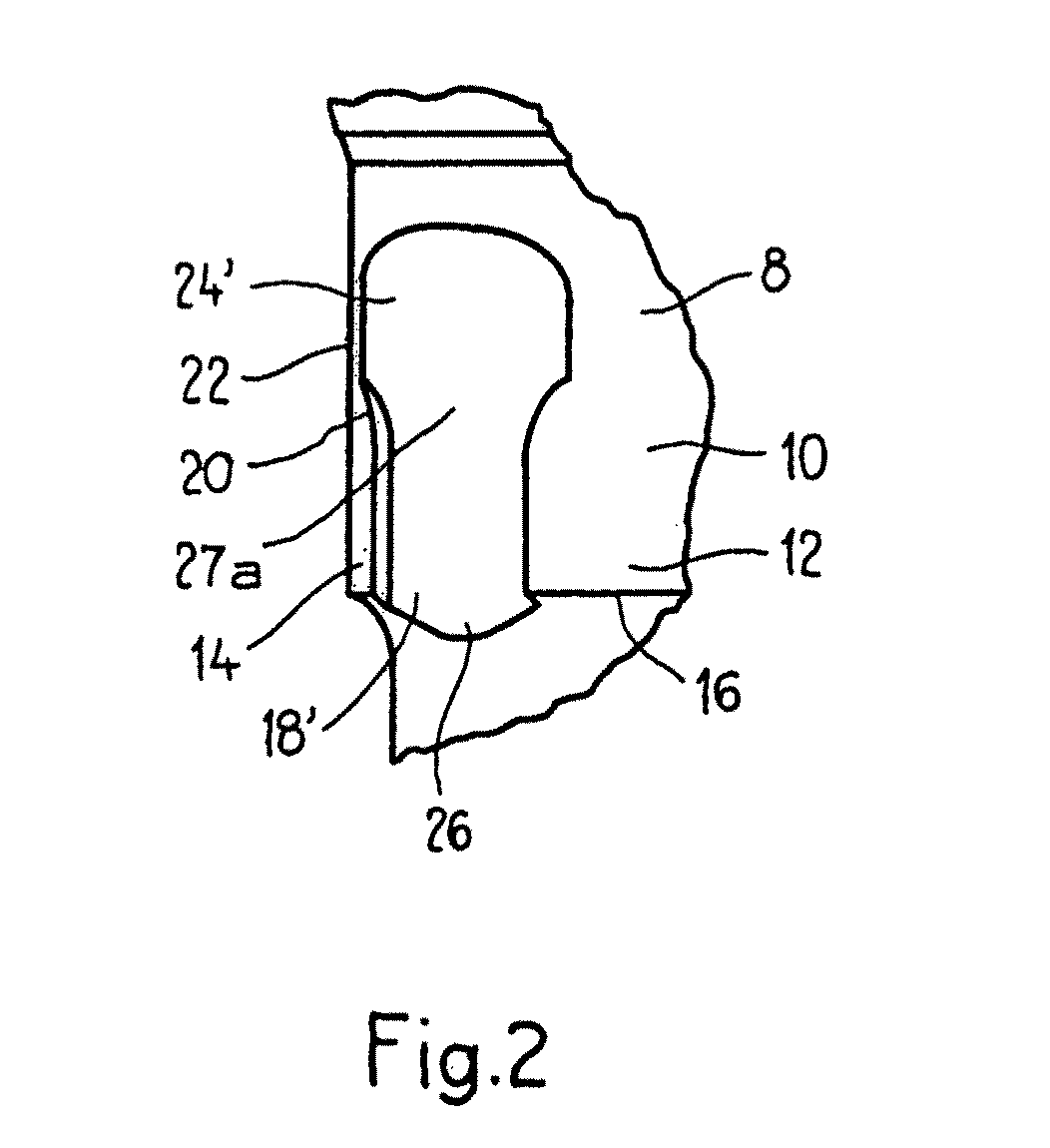
[0044]As is clear in particular from FIGS. 1 and 5 to 8, the abutment 2 of the present invention has an apical end 4, i.e. an end directed toward the bone in the implanted state, and a coronal end 6 arranged opposite the apical end. In the area of the apical end 4, the abutment 2 has an insert portion 8 which is designed to be received in an opening of a dental implant. The insert portion 8 comprises an anti-rotation segment 10 which, in its edge area 12 directed toward the apical end, has a groove portion 14. In the embodiment shown in the figures, the groove portion 14 has two diametrically opposite grooves 18′, 18″ which extend in the longitudinal direction from the apical edge 16 of the anti-rotation segment 10 and are of substantially constant cross section, as can be seen from FIG. 3, for example. The groove portion 14 is adjoined in the coronal direction by a transition portion 20 in which the width of the groove 18′, 18″ is continuously widened in order to merge into a bevel...


PUM


Abstract

Abutment for a dental implant (50), with an apical end (4) and with a coronal end (6) arranged opposite the apical end in the longitudinal direction. In the area of the apical end (4), the abutment has an insert portion (8) which is designed to be received by an opening of the dental implant and which has an anti-rotation segment (10) comprising at least one anti-rotation element (27) which is designed to cooperate with a corresponding mating anti-rotation element (53) of the dental implant (50). The anti-rotation element (27) comprises a groove (18′, 18″) which, from the edge of the anti-rotation segment (10) directed toward the apical end (4), extends in the coronal longitudinal direction along a groove portion (14) with a substantially constant groove width. The invention is characterized in that the groove (18′, 18″) is continuously widened in a transition portion (20) adjoining the groove portion (14), in order to merge into a bevel (24′, 24″) in a bevel portion (22) adjoining the transition portion (20).

Description

FIELD OF THE INVENTION[0001]The present invention relates to an abutment for a dental implant, a dental implant and a dental implant system comprising the abutment and the dental implant.BACKGROUND[0002]Two-part or multi-part dental implant systems are well known in the field of dental implantology. Such systems generally comprise a dental implant which has an outer thread and which is designed to be anchored in the bone of the patient, and an abutment (also called a secondary part) which serves as a base for the prosthetic structure. The abutment is often fitted in a corresponding coronal opening of the dental implant, i.e. an opening directed toward the crown of the tooth in the implanted state.[0003]A problem that often arises in multi-part dental implant systems of this kind concerns the correct positioning of the abutment in the dental implant. This problem has been considered in the following prior art documents, for example:[0004]U.S. Pat. No. 5,281,140 discloses a two-part a...

Claims


Application Information

Patent Timeline
IPC IPC(8): A61C13/225
CPCA61C8/005A61C8/0054A61C8/0066
Inventor BOEHLEN, RETO
Owner IVOCLAR VIVADENT AG
Why Eureka
Try Eureka