A shift gear driver of a flywheel synchronous transmission

A kind of transmission and synchronous technology, which is applied in transmission devices, gear transmission devices, clutches, etc., can solve the problems of cumbersome manufacturing of transmission structures, and achieve the effects of simple and reliable pre-synchronization, simple manufacturing, and high stability

Active Publication Date: 2013-07-31
HOERBIGER ANTRIEBSTECHN HLDG
View PDF7 Cites 2 Cited by
  • Summary
  • Abstract
  • Description
  • Claims
  • Application Information

AI Technical Summary

Problems solved by technology

[0004] But the transmission structures described in the prior art are still cumbersome to manufacture, since the two symmetrical annular discs must be fixe

Method used


Image

  • A shift gear driver of a flywheel synchronous transmission
  • A shift gear driver of a flywheel synchronous transmission
  • A shift gear driver of a flywheel synchronous transmission

Examples


Embodiment Construction

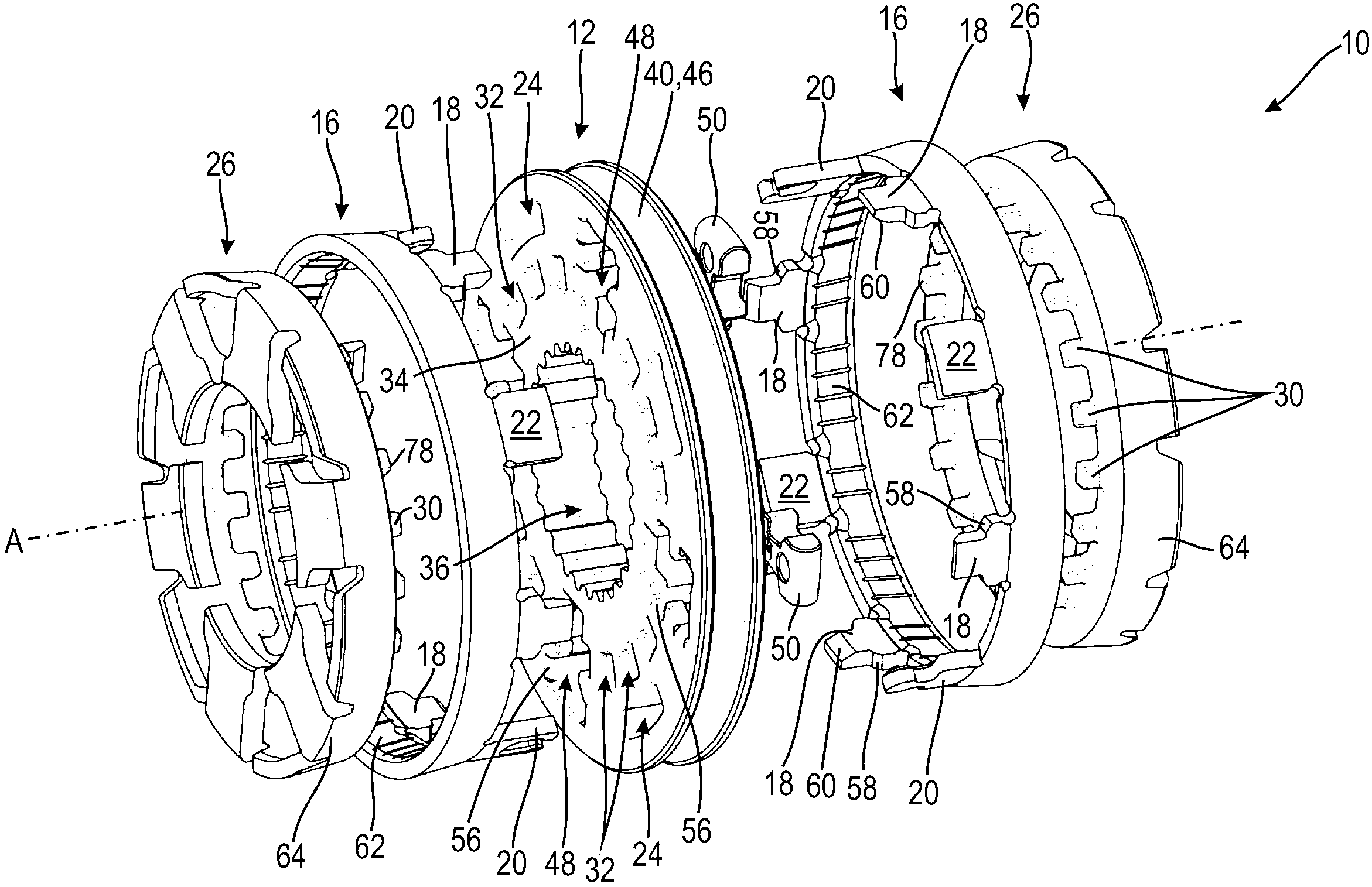
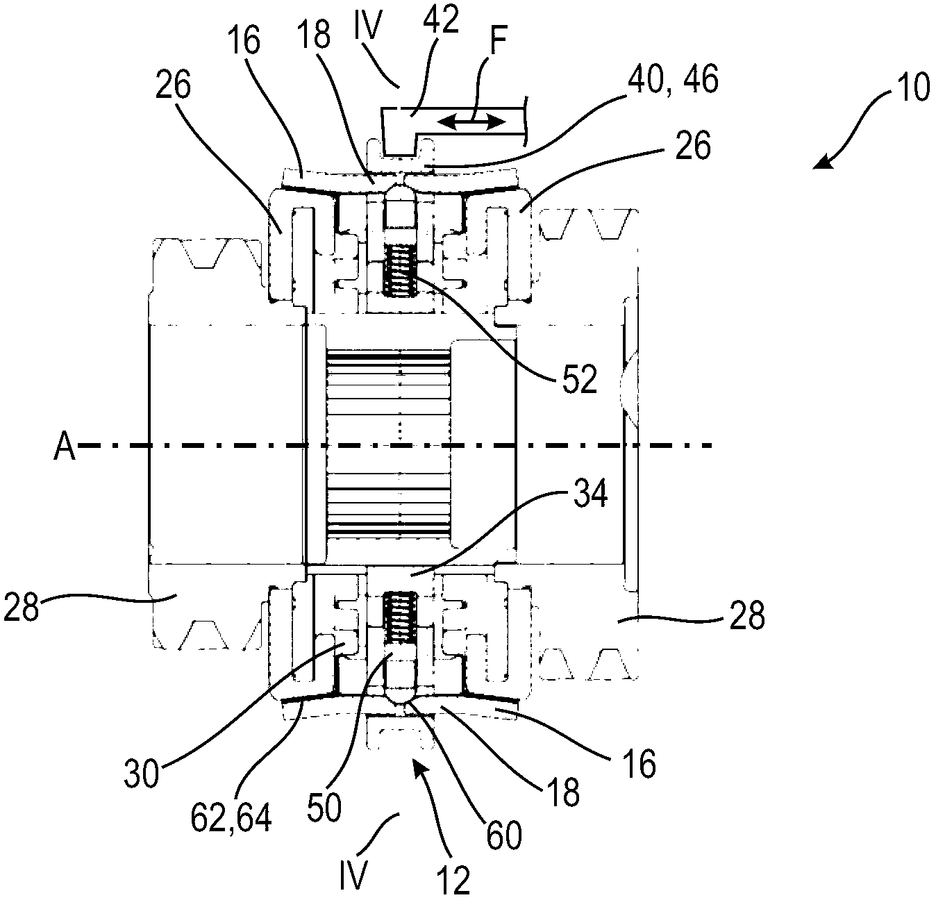
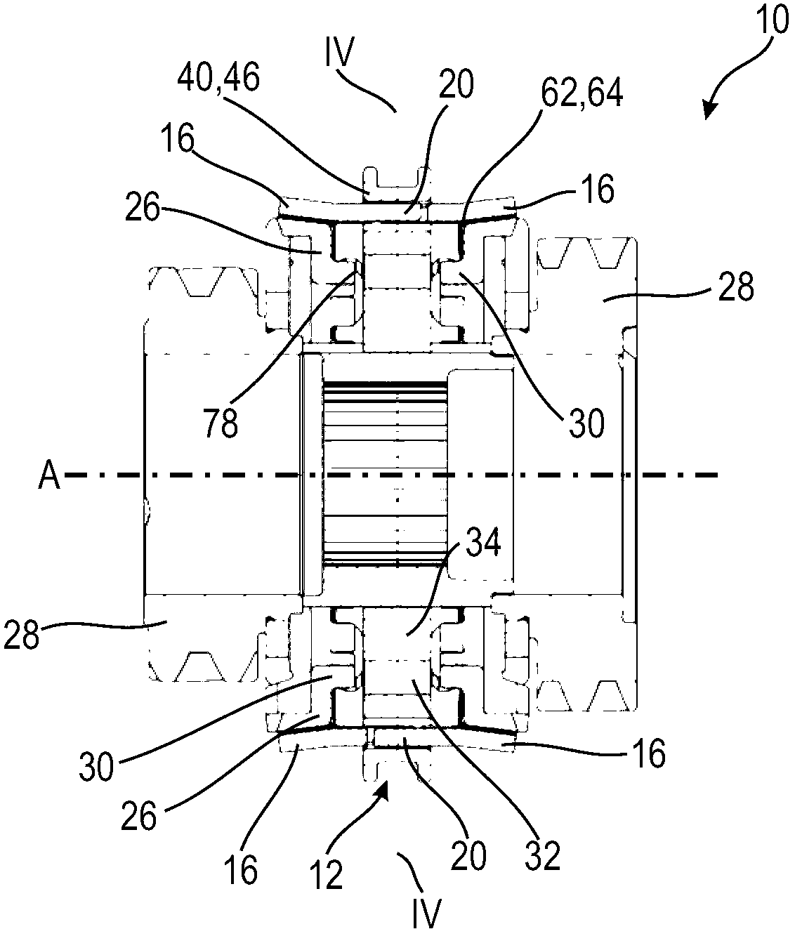
[0036] Figures 1 to 6 A first embodiment of an inertia-synchronous transmission 10 for a motor vehicle is shown, said transmission having an axially displaceable shift drive 12 according to the first embodiment, arranged on axially opposite sides of the shift drive 12 The two clutch bodies 26 on the side, and the two friction rings 16 that are also arranged on both axial sides of the shifting transmission 12 and coupled with the shifting transmission 12 along the circumferential direction 14, the clutch bodies can be arranged along the circumferential direction 14 Coupled in a rotationally fixed manner to the shifting drive 12 , the friction ring has axial projections 18 , 20 , 22 which can protrude into synchronizing recesses 24 of the shifting drive 12 .

[0037] Clutch body 26 is independent, but is respectively fixedly with the follower wheel 28 (referring to figure 2 and 3 ) connected components. In particular, the clutch body 26 is a profiled sheet metal part and is...


PUM


Abstract

The switching transmitter (12) has a one-piece annular body (34) rotatable around a transmission axis. The annular body has a contour (36) for rotationally fixed and axially movable coupling with a transmission shaft on its radial inner side and another contour (40) for axial coupling with an axially movable switching element on its radial outer side. The annular body has synchronization recesses (24) between the radial inner side and the radial outer side, where the axial extensions (18,20,22) of a friction ring (16) engage into the synchronization recesses. An independent claim is included for a lock-synchronized manual transmission with cams.

Description

technical field [0001] The invention relates to a shifting drive / transmitter for an inertia-synchronous transmission and to an inertia-synchronous transmission having such a shifting drive. Background technique [0002] In a conventional inertia synchronous transmission, a synchronous body and a separate shift sleeve that cooperates with the synchronous body are usually provided. Rotatable but axially displaceable. In order to simplify such transmissions in terms of construction and production technology, so-called "shift drives" are known in the prior art, which have annular bodies which are rotatable about a transmission axis. The annular body has a first contour on its radial inner side for a non-rotatable and axially displaceable coupling to the drive shaft, and a second contour on its radial outer side for the axially movable shifting element. Axial connection; and there is a synchronous notch between the radial inner side and the radial outer side, and each axial pro...

Claims


Application Information

Patent Timeline
IPC IPC(8): F16D23/08F16H3/12
CPCF16D23/0606
Inventor 彼得·埃希特勒
Owner HOERBIGER ANTRIEBSTECHN HLDG
Why Eureka
Try Eureka