Combustion chamber intermediate part for a gas turbine

a gas turbine and combustion chamber technology, applied in the direction of machines/engines, efficient propulsion technologies, lighting and heating apparatus, etc., can solve the problems of reducing the overall efficiency of the turbine, steep temperature rise in the individual combustion chambers, and exposing them to increased mechanical and thermal loads, so as to achieve the effect of lowering the cooling requirements

Active Publication Date: 2005-05-05
SIEMENS ENERGY GLOBAL GMBH & CO KG
View PDF8 Cites 2 Cited by
  • Summary
  • Abstract
  • Description
  • Claims
  • Application Information

AI Technical Summary

Benefits of technology

[0006] On the basis of this prior art, the object of the invention is to create a gas turbine in which the thermal and mechanical loads of the individual combustion chambers are significantly reduced in the transition section so that cooling requirements can be lowered in this area.

Problems solved by technology

One problem with this procedure is that in the area of the baffles embodied with comparatively small radii the hot gas flow hits the walls of the individual combustion chambers in the input area, exposing them to increased mechanical and thermal loads.
This leads to a steep temperature rise in the individual combustion chambers in the transition section, which in turn calls for increased cooling.
The pressure drops required to cool such an embodied transition section of the individual combustion chambers and the quantities of additional cooling gas required reduce the overall efficiency of the turbine and are therefore seen as disadvantageous.
In addition, the cooling arrangement shown in U.S. Pat. No. 4,719,748 for the individual combustion chambers calls for higher design costs as the chambers have to be provided with a double-shell casing along their entire length.

Method used


Image

  • Combustion chamber intermediate part for a gas turbine
  • Combustion chamber intermediate part for a gas turbine

Examples


Embodiment Construction

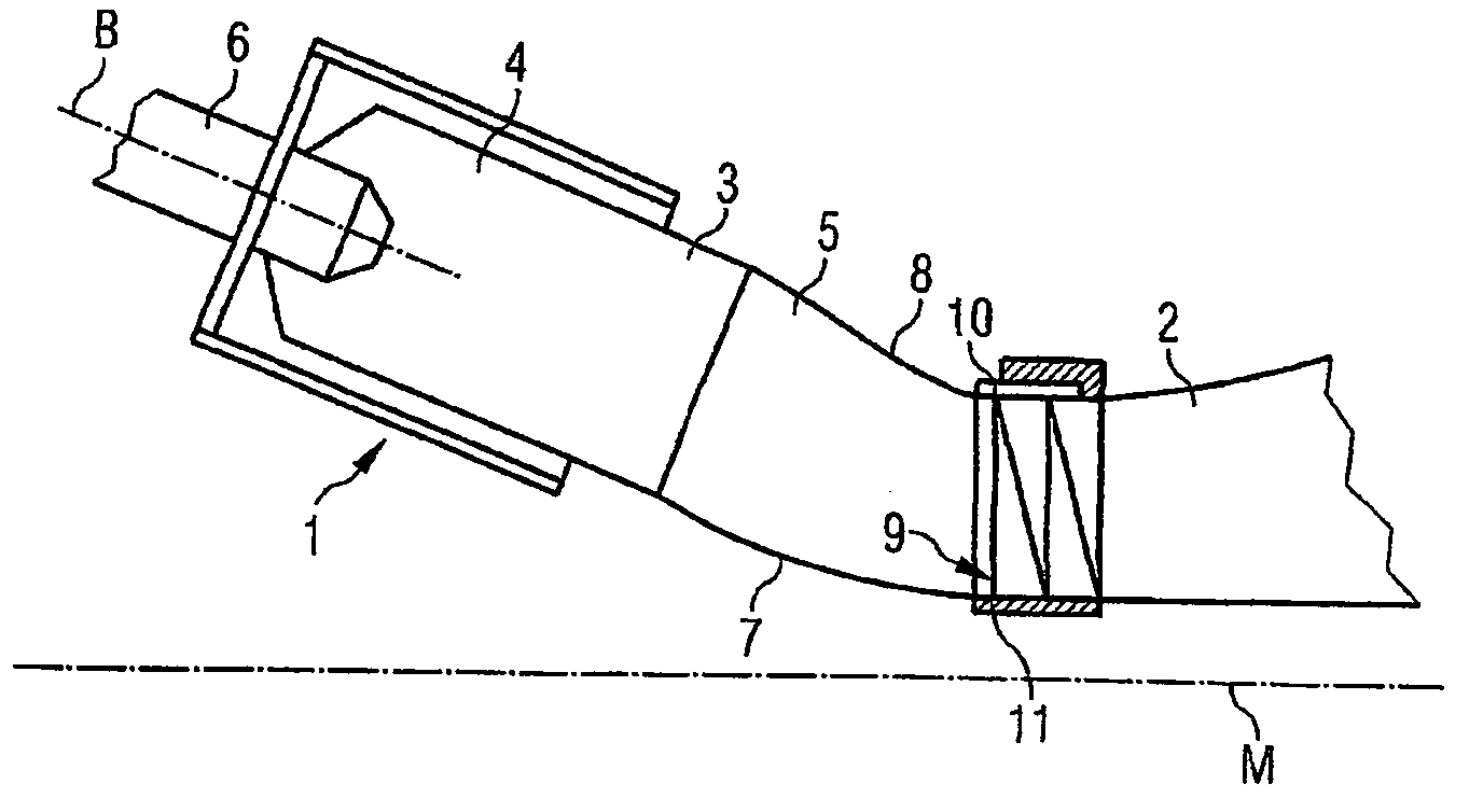
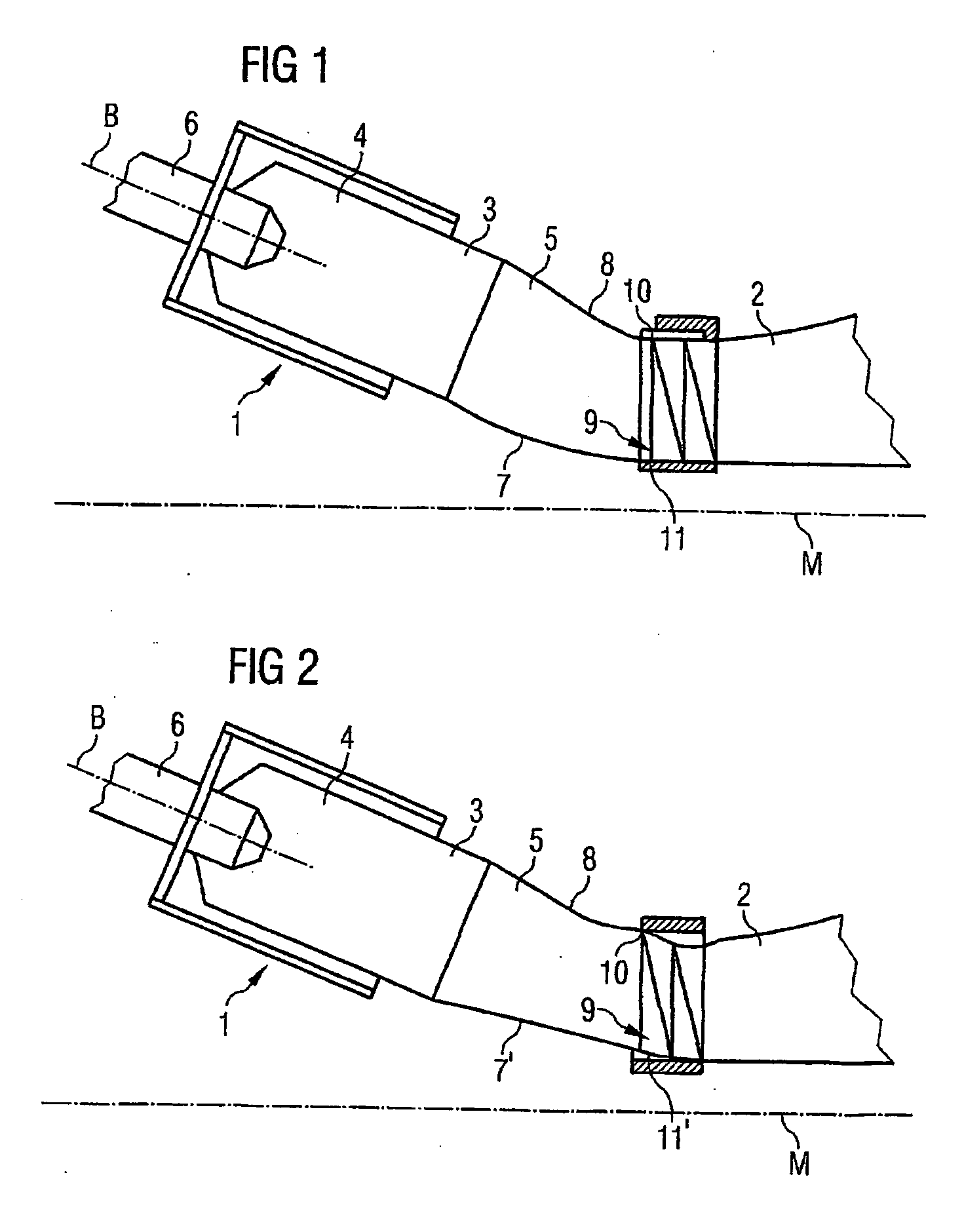
[0020]FIG. 1 shows a section of a turbine 1 in accordance with the invention in a first embodiment. In particular it shows an individual combustion chamber 3 in the transition to a turbine chamber 2 of the gas turbine 1. The individual combustion chamber 3 comprises an input section 4 and a transition section 5. The input section 4 is cylindrical with a circular base area; the transition section 5 changes the circular cross-section of the input section 4 in a cross-section with the form of a section of an annular segment. In the gas turbine 1 as per the invention there are a plurality of such individual combustion chambers 3 which on the output side of the transition sections 5 define an annular gap which leads to the turbine chamber 2.

[0021] Upstream of the individual combustion chamber 3 is a burner 6 which ignites a mixture of an oxygenated combustion gas and a fuel. Actual combustion then takes place in the individual combustion chambers 3 of the gas turbine 1, with resultant h...


PUM


Abstract

This invention relates to a gas turbine having a combustion chamber arrangement and a turbine chamber connected downstream of said combustion chamber arrangement, wherein the combustion chamber arrangement includes a plurality of individual combustion chambers formed by input areas and transition areas converging in an annular gap leading to the turbine chamber and wherein the longitudinal axes of the individual combustion chambers are placed at an angle relative to an engine axis that is defined by the axial extension of the turbine chamber. In order to improve said gas turbine by visibly reducing the thermal and mechanical loads of the individual combustion chambers in the transition area so that cooling requirements can be lowered in said area, the transition area of at least one individual combustion chamber into the turbine chamber is deflected in the direction of the engine axis and substantially in the input area of the turbine chamber.

Description

CROSS REFERENCE TO RELATED APPLICATIONS [0001] This application is the U.S. National Stage of International Application No. PCT / EP02 / 09615, filed Aug. 28, 2002 and claims the benefit thereof. The International Application claims the benefits of European application No. 01121088.7 EP filed Sep. 3, 2001, both of the applications are incorporated by reference herein in their entirety.FIELD OF INVENTION [0002] The invention relates to a gas turbine with a combustion chamber arrangement and a turbine chamber connected downstream of this combustion chamber arrangement, wherein the combustion chamber arrangement includes a plurality of individual combustion chambers formed by input sections and transition sections converging in an annular gap leading to the turbine chamber and wherein the longitudinal axes of the individual combustion chambers are placed at an angle relative to an engine axis that is defined by the axial alignment of the turbine chamber. BACKGROUND OF INVENTION [0003] Such...

Claims


Application Information

Patent Timeline
Patent Type & Authority Applications(United States)
IPC IPC(8): F23R3/42F01D9/02
CPCY02T50/675F01D9/023Y02T50/60
Inventor TIEMANN, PETEROLTMANNS, IRIS
Owner SIEMENS ENERGY GLOBAL GMBH & CO KG
Why Eureka
Try Eureka