
Pumping fluid delivery systems and methods using force application assembly

a technology of force application and pumping fluid, which is applied in the directions of special dispensing means, packaging goods types, volume measurement, etc., can solve the problems of difficult for patients to maintain the desired schedule, many potentially valuable medicines or compounds, including biologicals, are not orally active, and suffer from poor disassembly

Pending Publication Date: 2011-12-15
DEKA PROD LLP
View PDF11 Cites 86 Cited by
  • Summary
  • Abstract
  • Description
  • Claims
  • Application Information

AI Technical Summary

Benefits of technology

[0015]In a further related embodiment, actuating the force application assembly includes restricting retrograde flow toward the fluid source by occluding the inlet Alternatively or in addition, the method also includes preventing reverse flow of fluid from a dispensing chamber into the pumping chamber by using a passive valve placed therebetween.
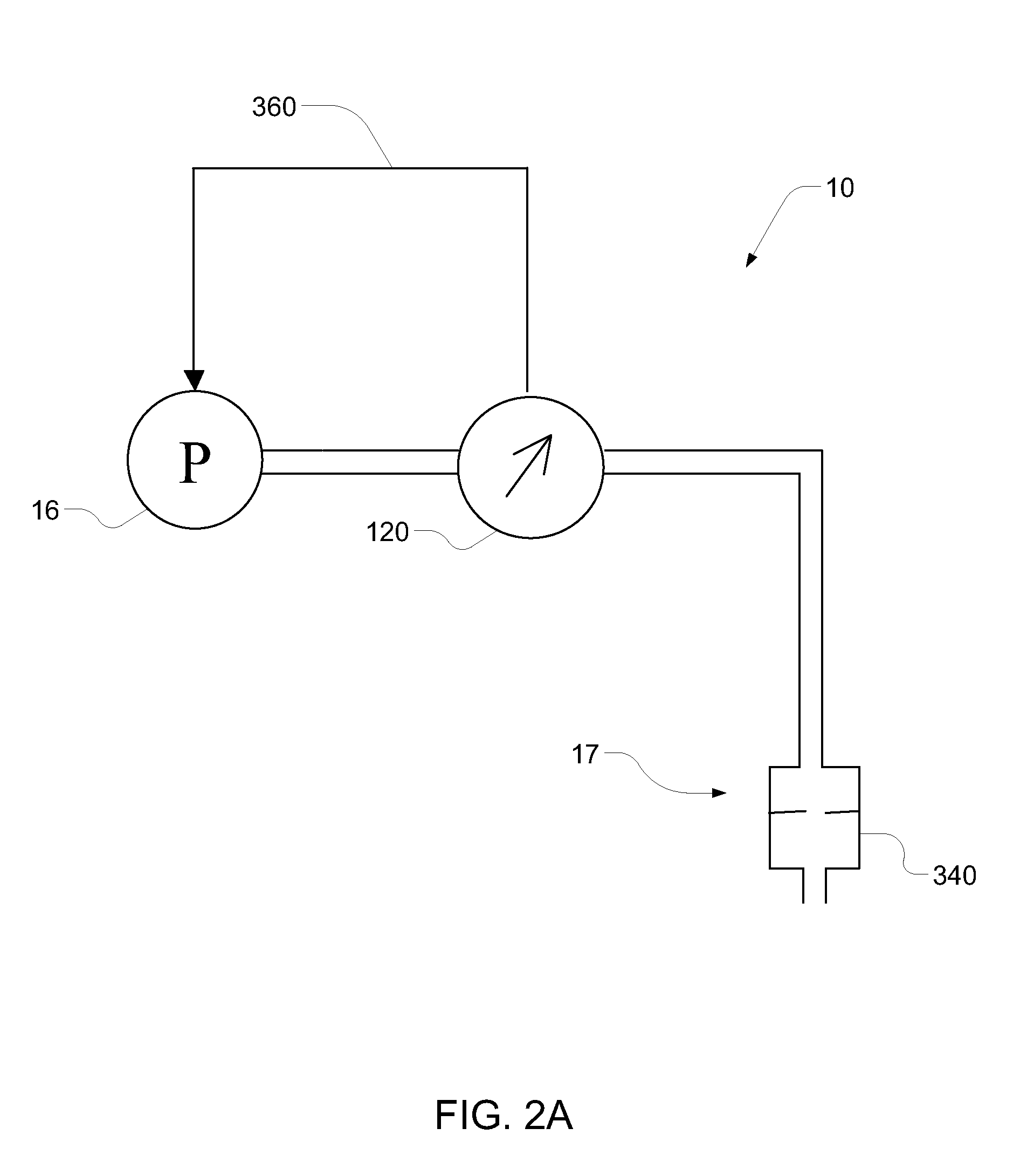
[0019]Alternatively or in addition, the method further includes causing fluid to flow downstream from the pump outlet through a tortuous flow-impeding conduit. The conduit may have various forms. It may have at least two turns. It may be coiled. It may have a serpentine shape. Optionally, the conduit has a length and an internal diameter selected to provide a predetermined impedance based on at least one of a viscosity and a density of the fluid. Optionally the internal diameter of the conduit is sufficiently large no as to prevent occlusion due to flow of the fluid through the conduit.
[0035]In a further related embodiment, the system additionally includes a tortuous high-impedance conduit located downstream of the dispensing assembly. The conduit may be implemented in a variety of ways. It may have at least two turns. It may be coiled. It may have a serpentine shape. Optionally, the conduit has a length and a internal diameter selected to provide a predetermined impedance based on at least one of a viscosity and a density of a fluid. Optionally, the internal diameter of the conduit is sufficiently large so as to prevent occlusion due to flow of a therapeutic liquid through the conduit.
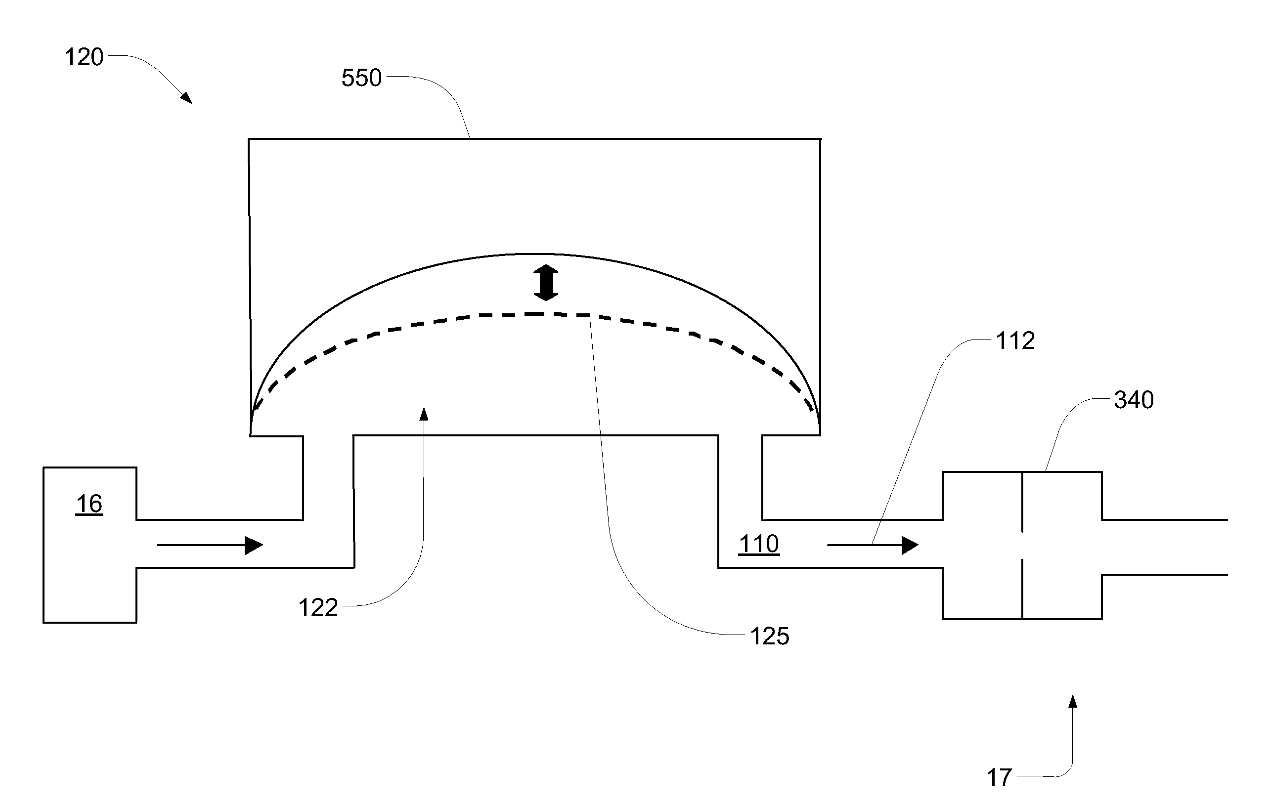
[0044]In another embodiment, the invention provides a valve for unidirectional flow. In this embodiment, the valve includes a first portion having an inlet and an outlet, the outlet having a circumferentially disposed valve seat; a second portion having a force application member; and a membrane separating the first and second portions. In this embodiment, the force application member applies a biasing force to sealingly hold the membrane against the valve seat so as to restrict flow to the outlet or from the outlet, unless fluid pressure in either the inlet or the outlet is sufficient to overcome the biasing force, thereby unseating the membrane from the valve seat and establishing flow through the valve. Also in this embodiment, when the membrane is sealingly held to the valve seat, fluid upstream of the inlet contacts a larger area of the membrane than does fluid downstream of the outlet, thereby giving greater mechanical advantage to the upstream fluid and causing the valve to open in response to a lower pressure at the inlet and to a higher pressure in the outlet, and encouraging unidirectional flow from the inlet and to the outlet,

Problems solved by technology

Many potentially valuable medicines or compounds, including biologicals, are not orally active due to poor absorption, hepatic metabolism or other pharmacokinetic factors.
Additionally, some therapeutic compounds, although they can be orally absorbed, are sometimes required to be administered so often it is difficult for a patient to maintain the desired schedule.
These devices suffer from a number of drawbacks including the malfunction rate.
Reducing the size, weight and cost of these devices is also an ongoing challenge,

Method used


Image

  • Pumping fluid delivery systems and methods using force application assembly
  • Pumping fluid delivery systems and methods using force application assembly
  • Pumping fluid delivery systems and methods using force application assembly

Examples


Embodiment Construction

[0178]Definitions. As used in this description and the accompanying claims, the following terms shall have the meanings indicated, unless the context otherwise requires:

[0179]A “user input” of a device includes any mechanism by which a user of the device or other operator can control a function of the device. User inputs may include mechanical arrangements (e.g., switches, pushbuttons), wireless interfaces for communication with a remote controller (e.g., RF, infrared), acoustic interfaces (e.g., with speech recognition), computer network interfaces (e.g., USB port), and other types of interfaces.

[0180]A “button” in the context of a user input such as the so-called “bolus button” discussed below may be any type of user input capable of performing a desired function, and is not limited to a pushbutton.

[0181]An “alarm” includes any mechanism by which an alert can be generated to a user or third party. Alarms may include audible alarms (e.g., a speaker, a buzzer, a speech generator), v...


PUM


Abstract

A disposable unit for a therapeutic fluid delivery device. The disposable unit includes a base portion comprising a reservoir cavity and a fluid path, the reservoir cavity including a reservoir port and a septum, the fluid path including a fluid channel from the reservoir port to a cannula port. The disposable unit also includes at least one flexible membrane portion attached onto said base portion and forming a top of said reservoir cavity and a top of said fluid channel and a tubing connected to said base portion at said cannula port, said tubing in fluid communication with said reservoir cavity.

Description

CROSS REFERENCE TO RELATED APPLICATIONS[0001]This application is a continuation of U.S. patent application Ser. No. 11 / 704,896, filed Feb. 9, 2007, now Publication No. US-2007-0219496, published Sep. 20, 2007, and entitled “Pumping Fluid Delivery Systems and Methods Using Force Application Assembly” (Attorney Docket No, 1062 / E71), the entirety of which is hereby incorporated herein by reference.[0002]Application Ser. No. 11 / 704,896 claims priority from the following U.S. Provisional Patent Applications, all of which are hereby incorporated herein by reference in their entireties:[0003]Provisional Application Ser. No. 60 / 772,313, filed Feb. 9, 2006 and entitled “Portable Injection System” (Attorney Docket No. 1062 / E42);[0004]Provisional Application Ser. No. 60 / 789,243, filed Apr. 5, 2006 and entitled “Method of Volume Measurement for Flow Control” (Attorney Docket No, 1062 / E53); and[0005]Provisional Application Ser. No. 60 / 793,188, filed Apr. 19, 2006 and entitled “Portable Injection...

Claims


Application Information

Patent Timeline
Patent Type & Authority Applications(United States)
IPC IPC(8): A61M5/142A61M5/00B67D7/08B67D7/14
CPCA61M2205/3331Y10T29/49826A61M2205/3546A61M2205/3576A61M2205/8237A61M2206/22A61M2209/045G05D7/0647G05D7/0676A61M5/14224A61M5/14248A61M5/14586A61M5/16809A61M5/16886A61M2005/14268A61M2205/0266A61M2205/0294A61M2205/18G08C17/02H04B7/2609A61M5/172A61M5/168G05B23/02A61M5/1452A61M5/14244A61M2207/00A61M5/158A61M5/1723A61M5/142Y10T29/49412Y10T29/49236Y10T29/494A61M2205/3375A61B5/0024A61B5/6833A61B2560/0412A61M5/1413A61M5/14212A61M5/14216A61M5/162A61M5/16804A61M5/16813A61M5/16831A61M5/365A61M5/5086A61M2005/1402A61M2005/14208A61M2005/14252A61M2005/14506A61M2005/1583A61M2005/1585A61M2005/1586A61M2005/16863A61M2205/04A61M2205/16A61M2205/3303A61M2205/3337A61M2205/3368A61M2205/3379A61M2205/3523A61M2205/3569A61M2205/3592A61M2205/50A61M2205/502A61M2205/52A61M2205/581A61M2205/582A61M2205/583A61M2205/8206A61M2230/201G01F22/00Y10T29/49828F04B43/02F04B43/09F04B43/1253F04B7/00F04C2230/60A61M5/3287B23P15/00A61B5/150022A61B5/150175A61B5/150358A61B5/150389A61B5/150503A61B5/15107A61B5/15117A61B5/15119A61B5/15121A61B5/15123A61B5/15125A61B5/15186A61M5/141A61M5/14232A61M5/148A61M5/152A61M2005/1581A61M2005/1726A61M2205/3334A61M2205/3341A61M2205/3389A61B5/1427A61J1/20
Inventor KAMEN, DEANGRAY, LARRY B.
Owner DEKA PROD LLP
Learn More