
Distal lock for a prosthetic hard socket

Active Publication Date: 2011-12-15
COYOTE O&P INC
View PDF2 Cites 11 Cited by
  • Summary
  • Abstract
  • Description
  • Claims
  • Application Information

AI Technical Summary

Benefits of technology

[0016]The invention comprises a lock for connecting a limb liner to a hard socket of a prosthetic leg or of a prosthetic arm. The preferred lock connects the distal end of the liner to the distal end of the socket, but the invented lock may be used in locations and positions on the liner and socket other than the distal ends / regions. The preferred distal lock is adapted to limit, and more preferably to prevent, air flow into the hard socket through the distal lock mechanism, even in instances wherein a vacuum pump is operated to create / maintain significant vacuum inside the socket. The preferred distal lock comprises a latch / unlatching system that is comfortable and convenient for the wearer, wherein swinging a latch handle unlatches the liner from the lock without any need for the user to push or pull a plunger or shaft.
[0018]The preferred embodiments of the invented distal lock comprise an axial bore in a lock housing that is adapted to be installed and secured in the distal end of the hard socket. A radial bore is also provided in the lock housing and intersects the axial bore. The axial bore is open, at its top, to the well of the hard socket, and a liner pin secured to the distal end of a roll-on liner may slide into the axial bore when the wearer dons the socket. The liner pin is locked in the axial bore by a lock blade or other protrusion that approaches the axial bore from the radial bore and engages the liner pin. Preferably, the liner pin has circumferential grooves or other indentations that each may receive the lock blade depending upon how far the liner-covered limb is inserted into the socket and the axial bore. The lock blade is captured in or on a shaft member that resides in the radial bore. When the distal lock is in the latched position, the lock blade protrudes far enough into the axial bore to contact and engage the liner pin by extending into one of said grooves / indentations, thus preventing upward axial movement of the pin relative to the axial bore, the housing, and, hence, the removal of the liner-covered limb from the hard socket.
[0022]Another object of the preferred embodiment is that the distal lock is compact and does not require elements that protrude a significant distance from the circumference of the lock housing during normal use of the lock in its latched state. When the lock is unlatched, the latch handle does protrude radially outward a significant distance, but, as soon as the lock is latched, the handle resides against and / or near the outer surface of the lock housing.

Problems solved by technology

This is because, with such a relatively low pressure inside the hard socket, there is a large driving force that would cause air flow into the hard socket through the distal lock, were it not effectively sealed.

Method used


Image

  • Distal lock for a prosthetic hard socket
  • Distal lock for a prosthetic hard socket
  • Distal lock for a prosthetic hard socket

Examples


Embodiment Construction

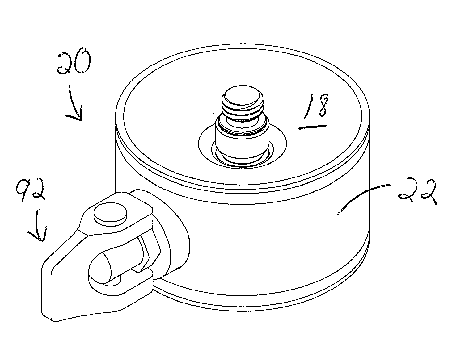
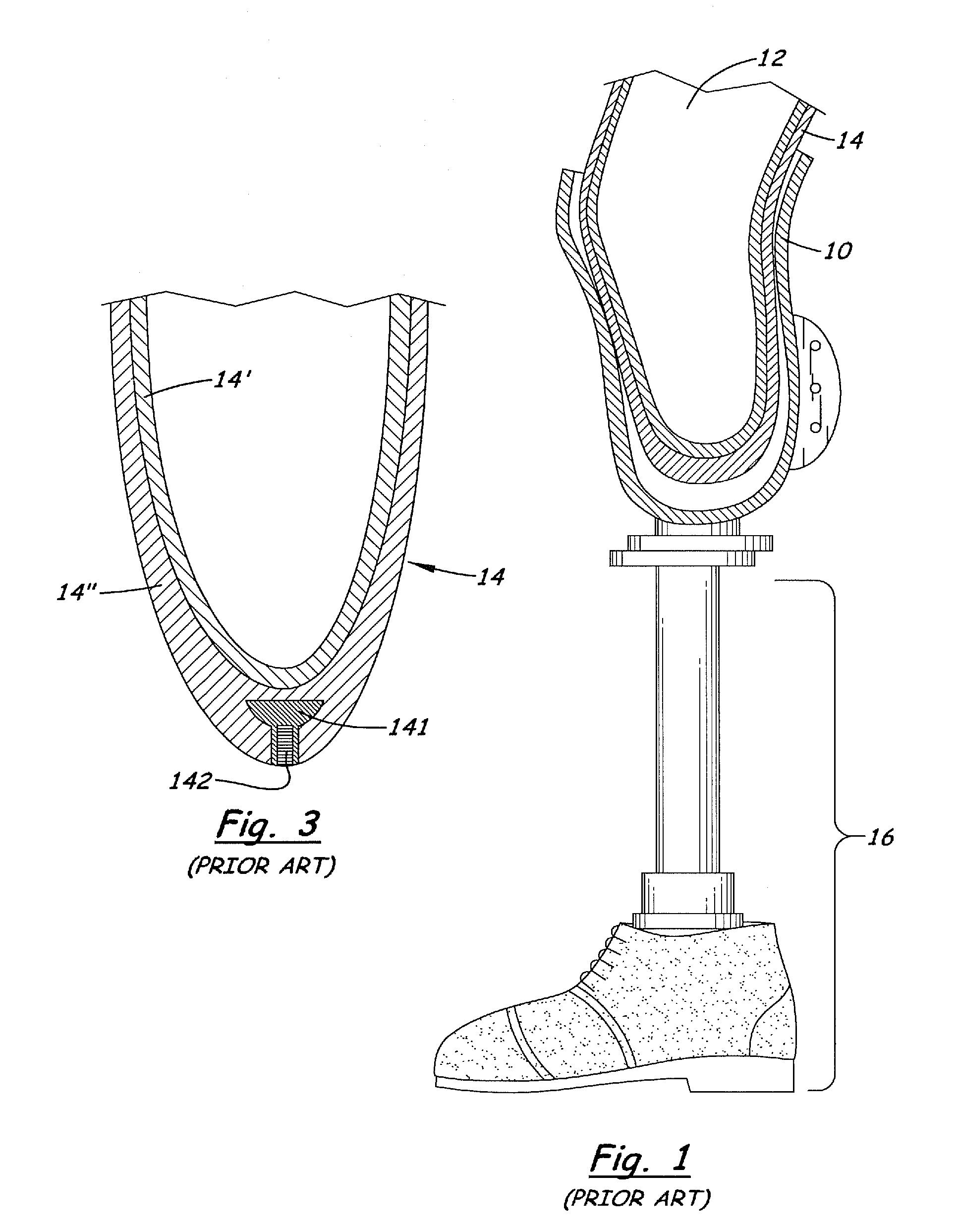
[0038]Referring to FIGS. 1-4, there are shown prior art systems for a leg prosthesis. Referring to FIGS. 5-13, there is shown one, but not the only, embodiment of the invented distal lock for a prosthetic limb hard socket. The preferred distal lock is especially beneficial for vacuum suspension, as it is adapted to block air flow through the distal lock unless and until the user or another person manually and purposely unlatches the distal lock. Alternatively, the distal lock, or adaptations of said distal lock, may be used for suction and / or other types of prosthesis suspension / connection, as desired by the wearer and / or judged optimal by the prosthetic technician.

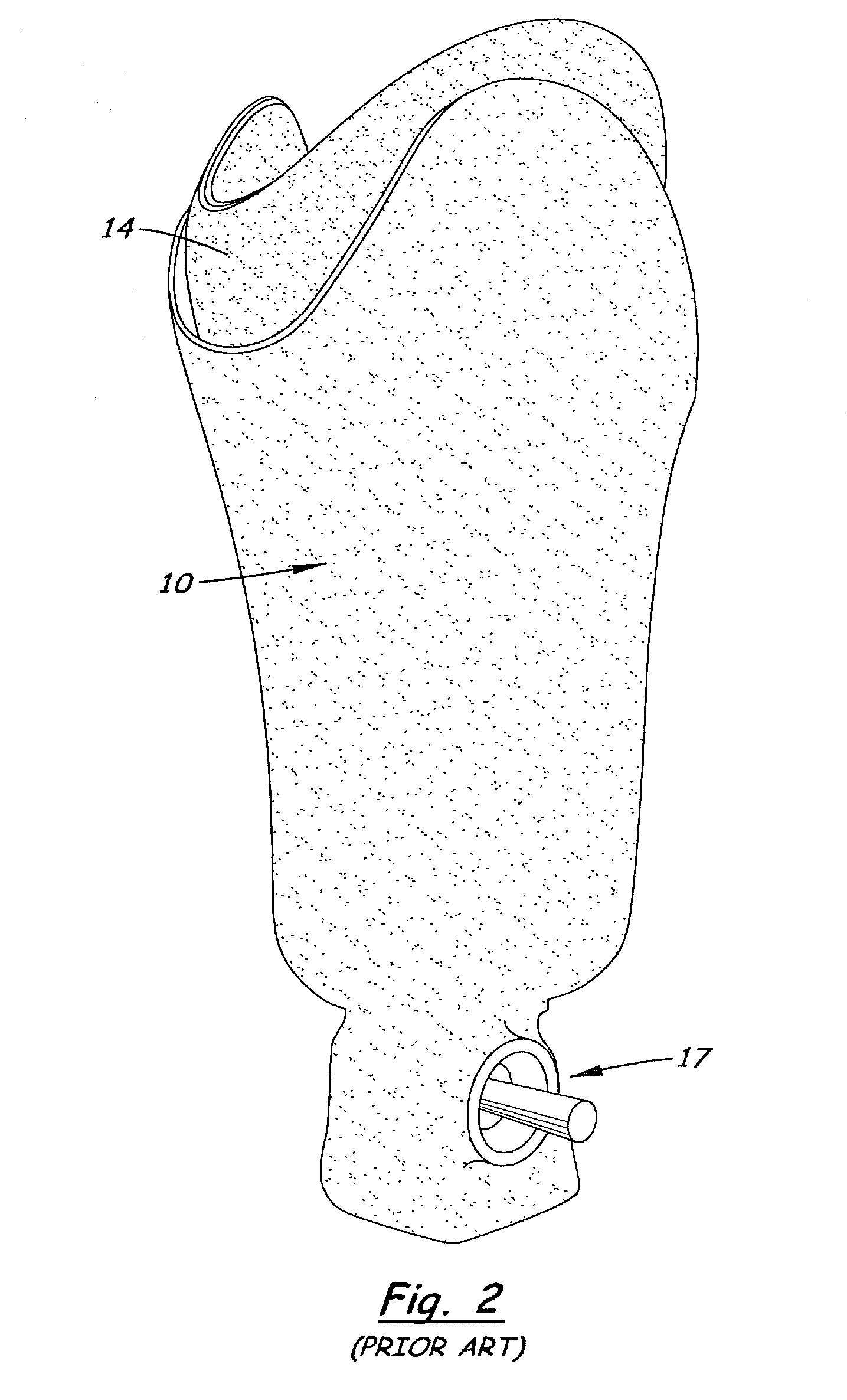
[0039]FIGS. 1-4 illustrate schematically a hard socket 10, limb 12 with roll-on liner 14 (preferably with gel layer 14′ and fabric layer 14″), and prosthetic foot portion 16. Connecting the foot portion 16 to the hard socket 10 is a distal lock 17, which may be molded into, or covered by, portions of the hard socket wall ...


PUM


Abstract

A lock connects the distal end of a liner to the distal end of the hard socket of a prosthetic leg, and limits or prevents air flow into the hard socket through the distal lock mechanism, even when vacuum is established inside the socket. The distal lock normally is latched, but can be conveniently unlatched by swinging a cammed latch handle. The liner pin may be inserted and locked into the distal lock, without the distal lock being unlatched and without losing the internal air seal preventing air flow through passages of the lock. A slidable, biased lock blade, and interaction between slanted surfaces of the blade and the liner pin, allow the pin to slide down, but not up, past the blade. The latch handle does protrude radially outward a significant distance, when the lock is unlatched, but, as soon as the lock is latched, the handle resides against and / or near the outer surface of the lock housing.

Description

[0001]This application claims benefit of Provisional Application Ser. No. 61 / 133,167, filed May 10, 2010, the entire disclosure of which is incorporated herein by this reference.BACKGROUND OF THE INVENTION[0002]1. Field of the Invention[0003]The present invention relates to external prosthetics, and more specifically to a lock system for securing a prosthetic hard socket to a socket liner worn on a residual limb. The preferred lock system connects the distal end of the liner to the distal end of the hard socket, and the preferred embodiments are adapted to prevent air flow into or out of the hard socket through the lock mechanism during normal use of the prosthetic limb. This way, pressure in the distal end of the interior well of the hard socket may be effectively controlled by other mechanisms, such as a vacuum pump and / or other mechanisms. When a vacuum fit is desired, as discussed elsewhere in this document, the pressure inside the hard socket may be controlled and adjusted accu...

Claims


Application Information

Patent Timeline
IPC IPC(8): A61F2/80
CPCA61F2/80A61F2002/805A61F2002/802A61F2002/7875
Inventor PERKINS, MATTDEAN, TRAVIS
Owner COYOTE O&P INC
Features
  • Generate Ideas
  • Intellectual Property
  • Life Sciences
  • Materials
  • Tech Scout
  • Unparalleled Data Quality
  • Higher Quality Content
  • 60% Fewer Hallucinations
Learn More