Automatic grain transfer control system based on real time modeling of a fill level profile for regions of the receiving container

a technology of automatic grain transfer control and real-time modeling, applied in the field of grain transfer control system, can solve the problems of missing alarms or warnings, unable to monitor continuously, and risk of deviation from the desired travel path or swath

Active Publication Date: 2011-12-15
CNH IND AMERICA LLC
View PDF3 Cites 61 Cited by
  • Summary
  • Abstract
  • Description
  • Claims
  • Application Information

AI Technical Summary

Benefits of technology

[0006]What is disclosed is a grain transfer control system which provides one or more of the

Problems solved by technology

This situation is problematic because both operators typically must look backward towards the unloading tube while driving forward when unloading on the go.
The combine operator cannot continuously monitor the field and machine conditions, resulting in a risk of deviation from the desired travel path or swath, collision with unexpected obstacles in front of the combine, and/or missing alarms or warnings displayed inside the combine.
In addition, neither operator is situated to readily view the inside of the receiving container so visually monitoring the fill level of the container is typically not possible.
Achieving an even fill of a stationary receiving container is problematic because of the increasing size of the receiving containers, which can typically hold several times the capacity of the combine

Method used


Image

  • Automatic grain transfer control system based on real time modeling of a fill level profile for regions of the receiving container
  • Automatic grain transfer control system based on real time modeling of a fill level profile for regions of the receiving container
  • Automatic grain transfer control system based on real time modeling of a fill level profile for regions of the receiving container

Examples


Embodiment Construction

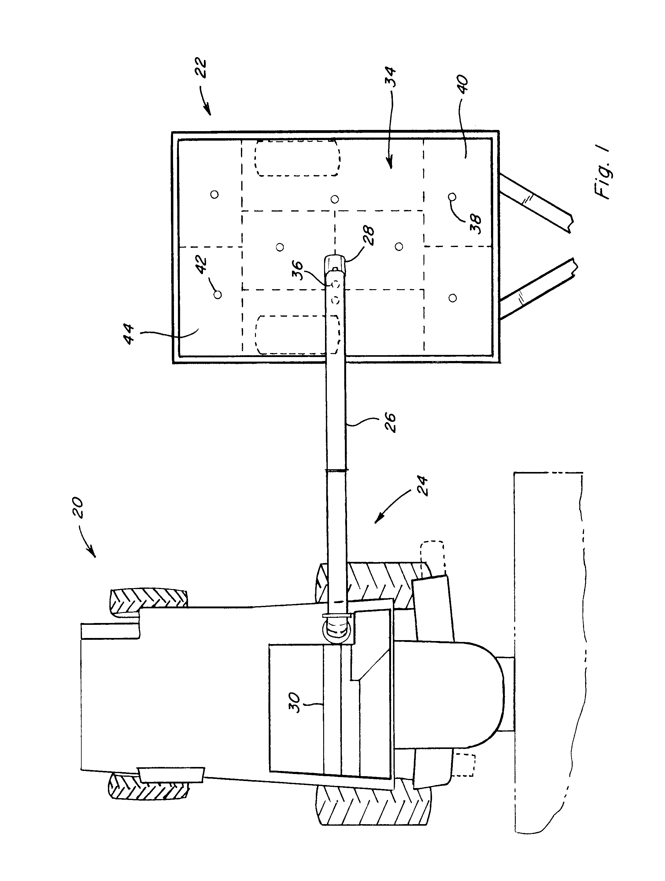
[0033]Referring now to the drawings, wherein like numbers refer to like items, FIG. 1 depicts a representative agricultural harvesting work machine, which is shown here as a combine 20, including an unloading system 24 of well-known construction and operation. A cylindrical shaped unloading tube 26 including a discharge nozzle 28 is shown in a deployed or unloading position for unloading crop material into an accompanying container, which here is illustrated by a conventional grain receiving container 22, situated in a generally side by side relationship with combine 20, in the well-known manner. This is intended to be representative of a wide variety of unloading operations, wherein a known rate of flow of grain from combine 20 is to be directed into a receiving container, such as receiving container 22, periodically during operation of combine 20. When not in use, unloading tube 26 is stored in a position extending rearwardly (not shown) from combine 20, also in the well known man...


PUM


Abstract

A grain transfer control system for automatically controlling relative positions of an unloading system discharge nozzle of a work machine and a receiving container based on a real time model of a fill level profile for regions of the receiving container, the profile being modeled using known or estimated rates of flow of grain and positions of the nozzle relative to regions of the receiving container as a function of time, the system adjusting the relative positions of the nozzle and the receiving container to effect a generally even fill of the receiving container.

Description

TECHNICAL FIELD[0001]The present invention relates to a grain transfer control system for transferring a flow of grain from a work machine to a receiving container, and more particularly to a system including real time modeling of a fill level profile for regions of the receiving container based on known or estimated rates of the flow of grain and positions of an unloading system discharge nozzle relative to the regions of the receiving container as a function of time, the grain transfer control system automatically adjusting relative positions of the discharge nozzle and the receiving container to effect a generally even fill of the receiving container.BACKGROUND ART[0002]Harvesting operations in a large field typically involve unloading grain from a harvester, such as a combine, to a receiving container, such as a tractor pulled grain cart, bin, or the like. Relevant information that should be considered during the unloading process includes, but is not limited to, crop type; weat...

Claims


Application Information

Patent Timeline
IPC IPC(8): G06F7/00B60P1/00
CPCA01D41/127A01D43/087A01D41/1217
Inventor PIGHI, OSMANPAQUET, BERT J.F.
Owner CNH IND AMERICA LLC
Why Eureka
Try Eureka