Braking/driving control apparatus for vehicle

Active Publication Date: 2011-12-15
ADVICS CO LTD +1
View PDF3 Cites 17 Cited by
  • Summary
  • Abstract
  • Description
  • Claims
  • Application Information

AI Technical Summary

Benefits of technology

[0007]The present invention has been made in view of the above circumstances, and it is an object of the present invention to reduce the possibility that the vehicle slides down due to an error in an estimated road gradient in a technique of suppressing sliding-down of a vehicle on an uphill road.
[0008]In order to achieve the above object, there is provided a braking/driving control apparatus for a vehicle includes: a basic control unit which calculates and outputs a target axle torque based on a target acceleration set as an acceleration of the vehicle to be achieved and a driving resistance of the vehicle including an effect of gravity according to a gradient of a road, and which determines an axle torque to be required for a power train of the vehicle and an axle torque to be required for a braking apparatus of the vehicle based on the calculated target axle torque; a sliding-down prediction determining unit which determines whether there is a possibility that the vehicle slides down rearwards on an uphill road, during deceleration of the vehicle; and a sliding-down preventing process executing unit which performs a process for reducing a possibility that the vehicle slides down, based on a determination result of the sliding-down prediction determining unit. Until the sliding-down prediction determining unit determines that there is a possibility that the vehicle slides down rearwards on an uphill road, the sliding-down preventing process executing unit controls the basic control unit to calculate and output the target axl

Problems solved by technology

However, if the estimated road gradient has an error by even little amount, a target axle torque could be set to be larger than necessary tor

Method used


Image

  • Braking/driving control apparatus for vehicle
  • Braking/driving control apparatus for vehicle
  • Braking/driving control apparatus for vehicle

Examples


Example

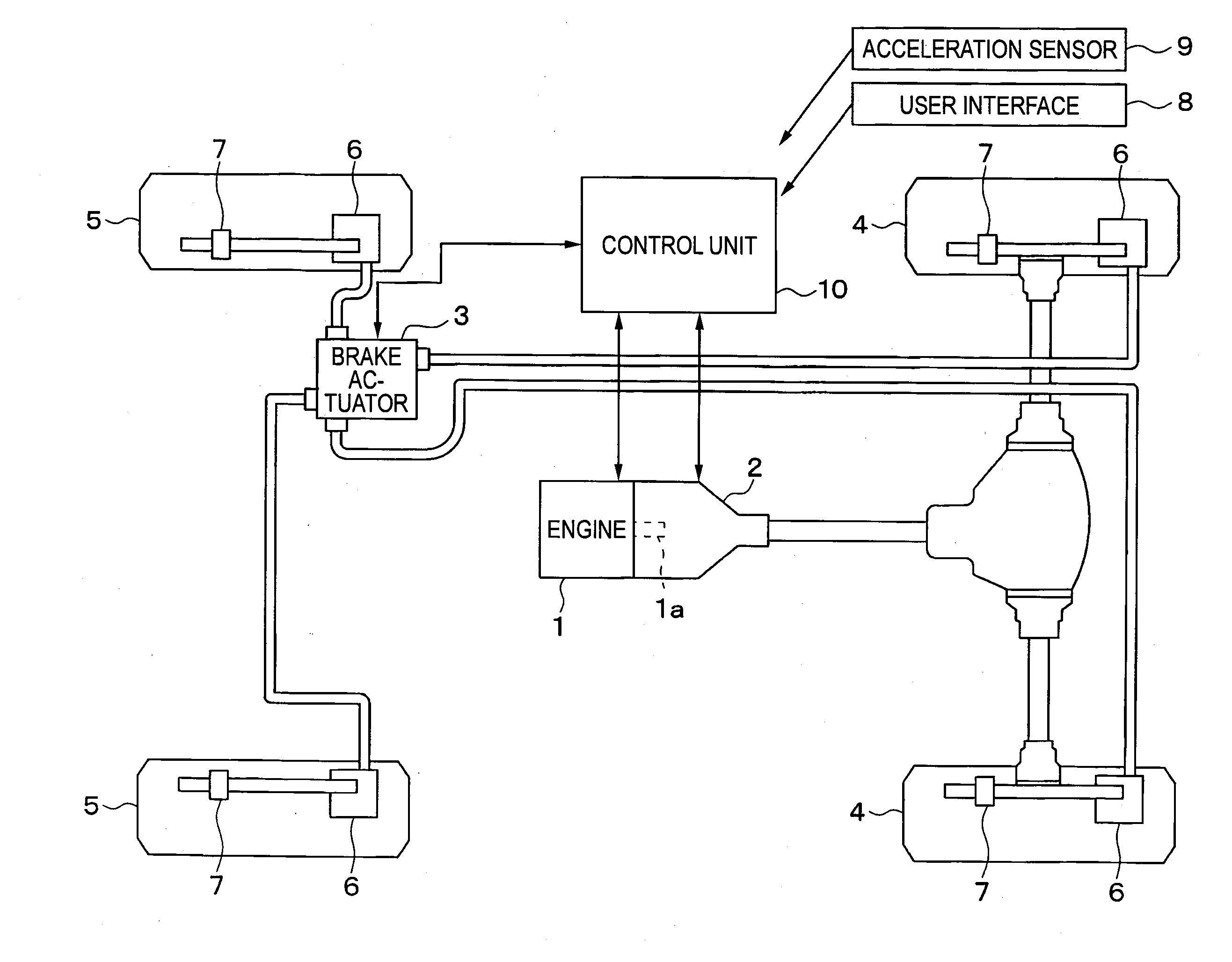
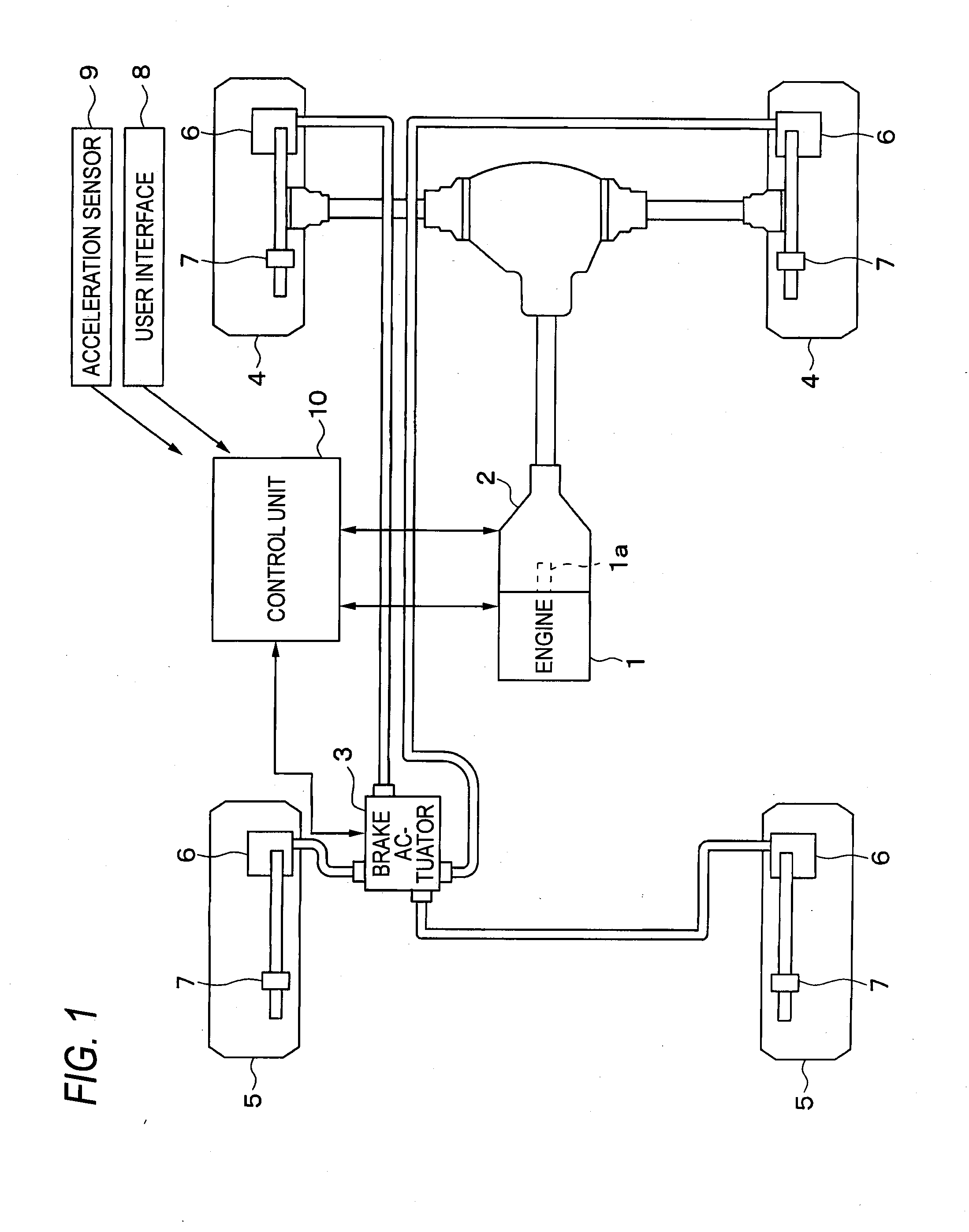
[0017]Hereinafter, a braking / driving cooperation system for a vehicle according to an illustrative embodiment of the present invention will be described. FIG. 1 shows a whole configuration of a braking / driving cooperation system for a vehicle. The braking / driving cooperation system for a vehicle has an engine 1, which is a gasoline internal combustion engine, an automatic transmission 2, a brake actuator 3, wheel cylinders 6 and wheel speed sensors 7 mounted for wheels 4, 5, respectively, a user interface 8, an acceleration sensor 9, a control unit 10 and the like.

[0018]A crankshaft 1a of the engine 1 is connected with the automatic transmission 2. Rotating force of the crankshaft 1a is varied by the automatic transmission 2 and is then transmitted to the driving wheels 4. Engine torque of the engine 1 and a gear ratio of the automatic transmission 2 are controlled by the control unit 10.

[0019]The driving wheels 4 or the driven wheels 5 are applied with braking force by the hydrauli...


PUM


Abstract

A braking/driving control apparatus for a vehicle includes a basic control unit which calculates and outputs a target axle torque based on a target acceleration and a driving resistance of the vehicle and which determines an axle torque for a power train of the vehicle and an axle torque for a braking apparatus of the vehicle based on the calculated target axle torque, a sliding-down prediction determining unit which determines whether there is a possibility that the vehicle slides down rearwards on an uphill road, and a sliding-down preventing process executing unit which performs a process for reducing a possibility that the vehicle slides down, based on a determination result of the sliding-down prediction determining unit. After the sliding-down prediction determining unit determines that there is the possibility, the sliding-down preventing process executing unit controls the basic control unit to calculate and output the target axle torque so as to reach an axle torque which is obtained by reducing a predetermined positive amount form an estimated value of an axle torque necessary for the vehicle to achieve the target acceleration against the driving resistance.

Description

CROSS REFERENCE TO RELATED APPLICATIONS[0001]This application is based on and claims priority under 35 U.S.C. §119 to Japanese Patent Application 2010-132799, filed on Jun. 10, 2010, the entire content of which is incorporated herein by reference.BACKGROUND[0002]1. Field of the Invention[0003]The present invention relates to a braking / driving control apparatus for a vehicle.[0004]2. Description of Related Art[0005]JP-A-2009-040308 describes a technique of suppressing sliding down of a vehicle on an uphill road. Specifically, there is provided a vehicle control apparatus for controlling driving force, which estimates a gradient of the uphill road and generates braking force according to the estimated road gradient, thereby suppressing the sliding down of the vehicle.[0006]However, if the estimated road gradient has an error by even little amount, a target axle torque could be set to be larger than necessary torque (i.e., an amount of braking might be insufficient). In this case, the ...

Claims


Application Information

Patent Timeline
IPC IPC(8): B60T8/17B60W10/04B60W10/06B60W10/18B60W10/184B60W30/00B60W30/18B60W40/02B60W40/10
CPCB60T7/122B60T2201/06B60W10/06B60W10/188B60W30/18027Y10T477/6422B60W2510/0657B60W2510/1005B60W2510/105B60W2510/182B60W2550/142B60W30/18118B60W2552/15
Inventor TAKEDA, MASAYOSHIMARUYAMA, MASAKIMORI, YUKIOTANIGUCHI, KAZUYATOKUMOCHI, DAISUKE
Owner ADVICS CO LTD
Why Eureka
Try Eureka