
Milking arrangement for animals

Inactive Publication Date: 2011-12-22
DELAVAL HLDG AB
View PDF10 Cites 18 Cited by
  • Summary
  • Abstract
  • Description
  • Claims
  • Application Information

AI Technical Summary

Benefits of technology

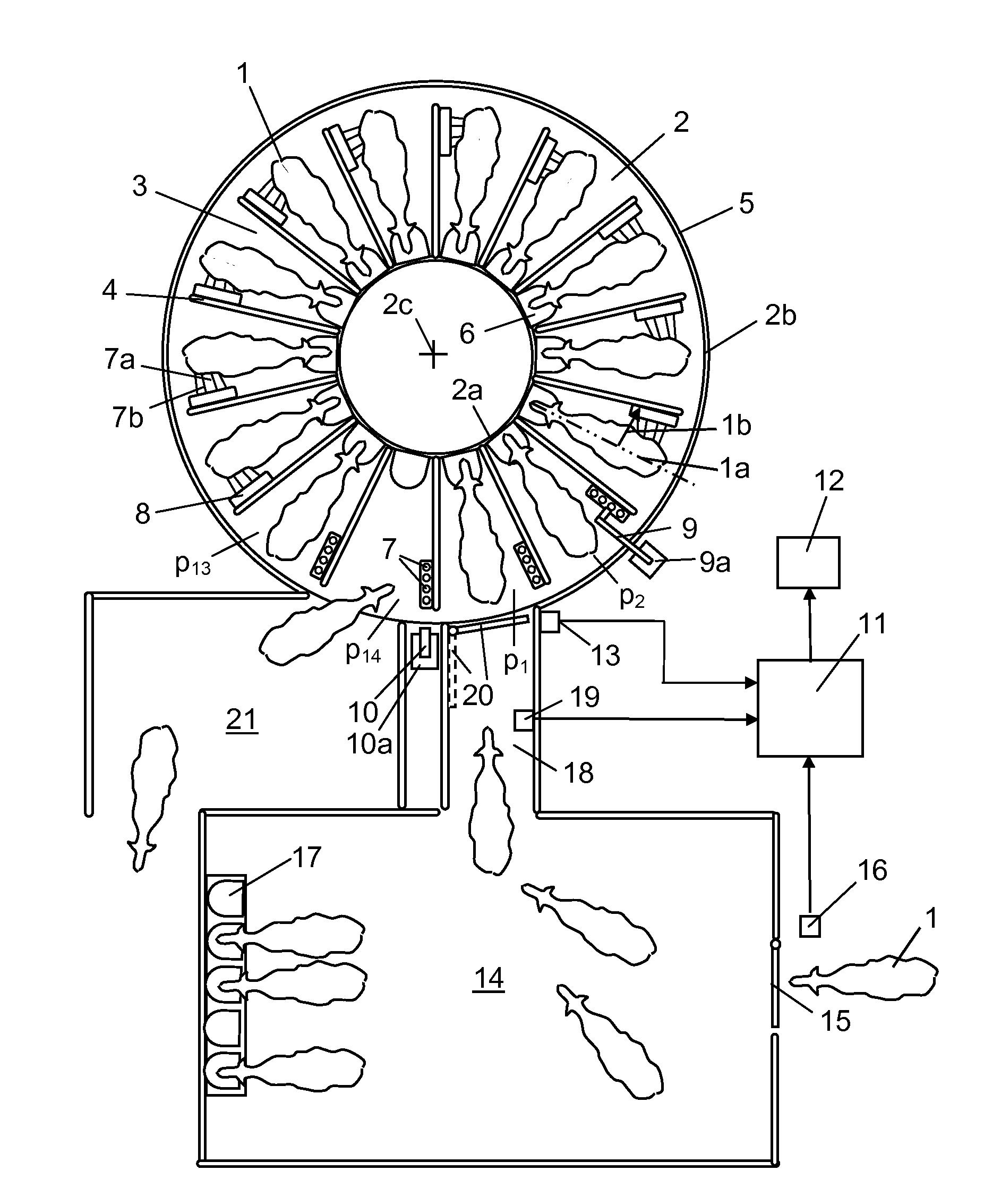
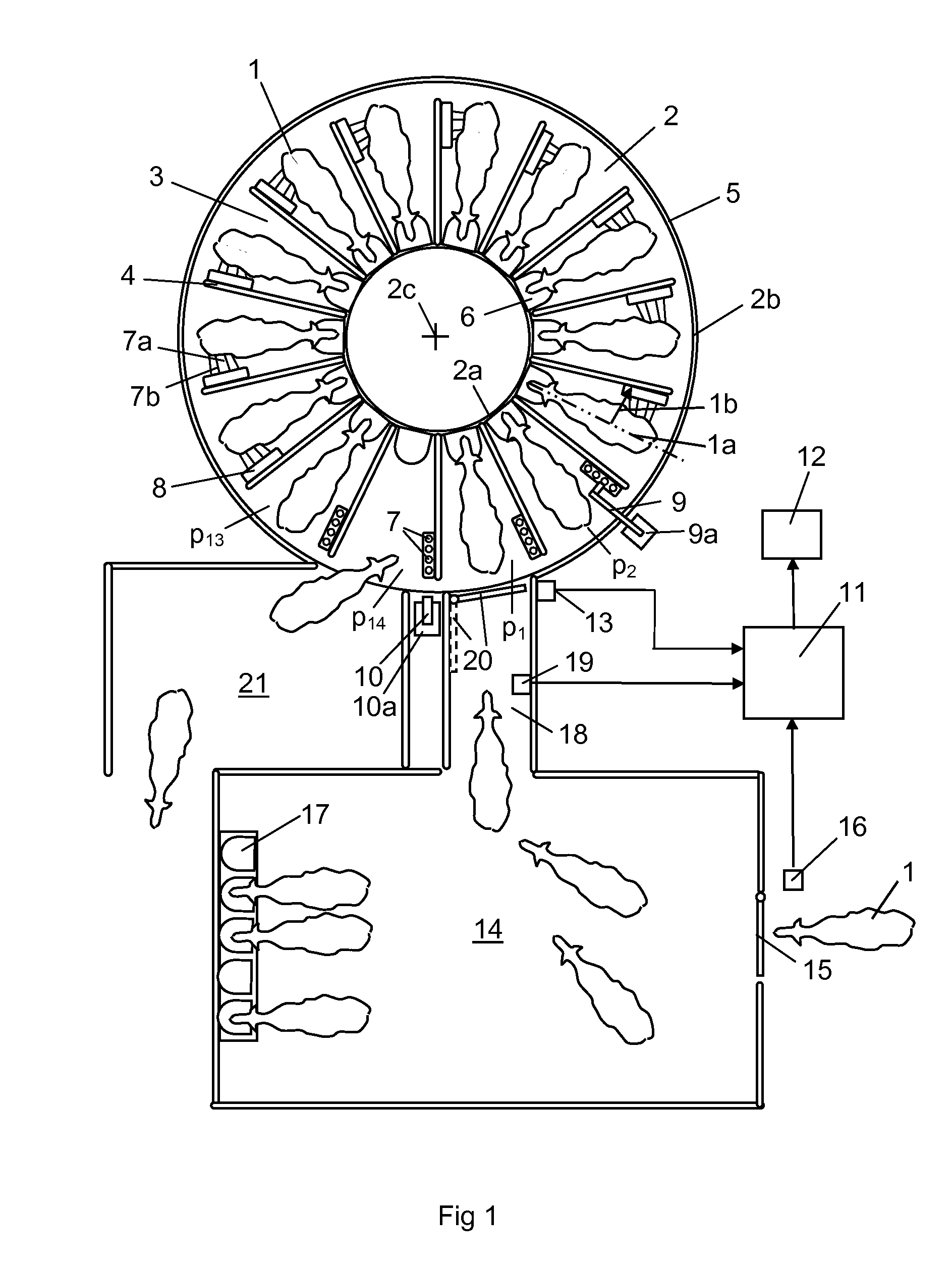
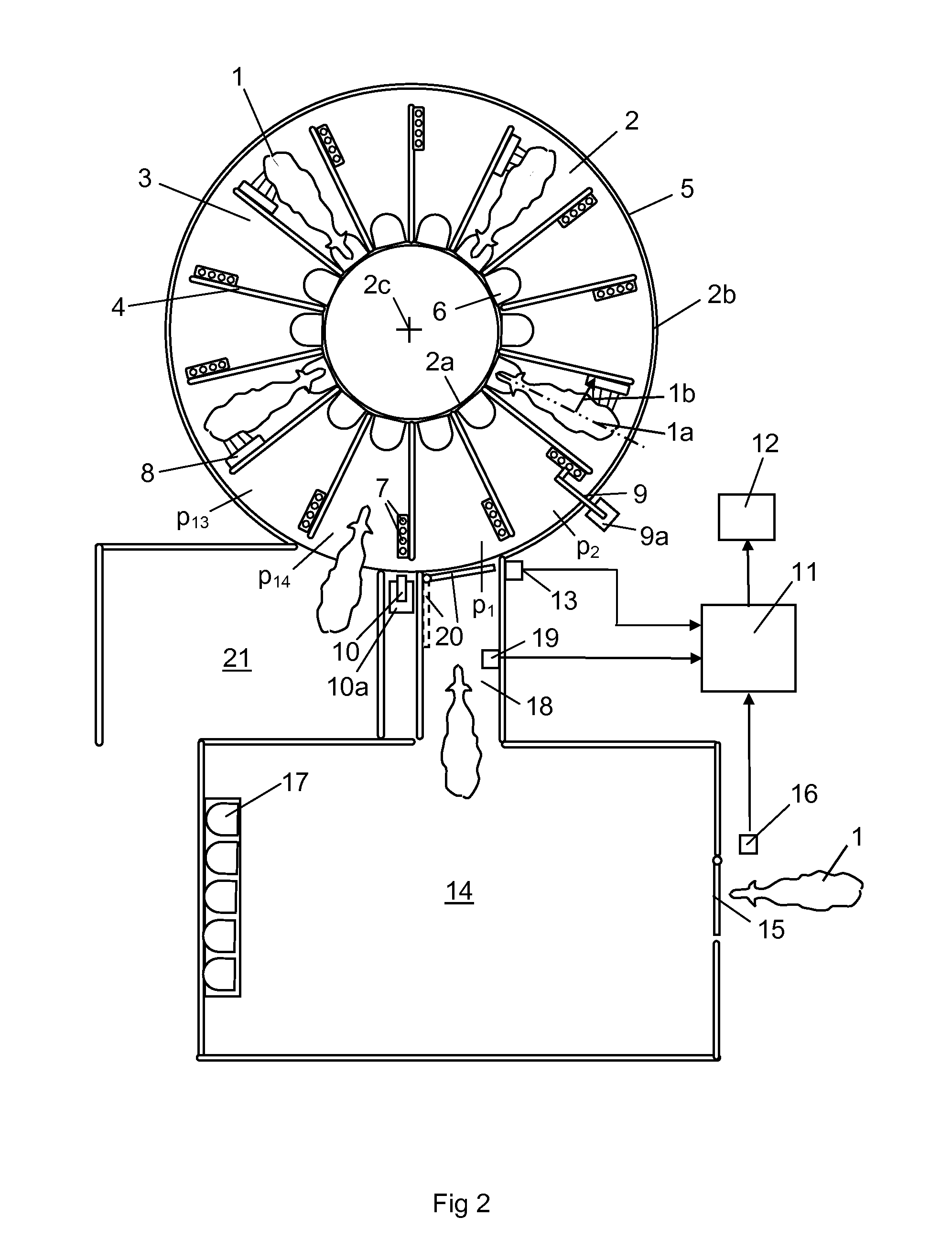
[0008]According to a preferred embodiment of the invention, the milking arrangement comprises a waiting area which the animals have to enter before they are allowed to enter a milking stall on the platform. Such a waiting area is possible to use in milking arrangements based on voluntary animal traffic or in parlours where batch milking is practised where an operator brings the animals to the waiting area. The waiting area may contain concentrated food. The supply of concentrated food results in an increased animal traffic to the milking arrangement. The control unit may be adapted to estimate the number of animals to enter the milking stalls by means of information from detection sensors which detects when an animal enters and leaves the waiting area. By means of such information, the control unit is able to calculate the numbers of animals in the waiting area and the numbers of animals to enter the platform during a future period of time. Alternatively or in combination, the control unit may be adapted to estimate the numbers of animals to enter the milking stalls by means of historical information about the visiting frequency of the animals. If batch milking is practised, a certain number of animals may be milked at predetermined times or with predetermined time intervals. The control unit may be adapted to estimate the numbers of animals to enter the milking stalls during a period of time by means of historical information about the visiting frequency for a corresponding period of time. The animal traffic to the milking arrangement is, for example, considerably lower during the night than during the day. The animal traffic to the milking arrangement varies even during different periods of the day and the night. Thus, it is possible to estimate the animal traffic to the rotary platform by means of statistical data for a herd with a good accuracy.
[0011]According to a further embodiment of the invention, said positioning means are adapted to position the animals in milking stalls on the platform with their heads in the vicinity of an inner periphery of the annular platform. In such a case, the animals may have an extension in a completely radial direction on the annular platform or be arranged in a herringbone pattern. In this case, the positioning means may comprise fence arrangements having a substantially radial extension on the annular platform dividing the platform into milking stalls. Alternatively, said positioning means are adapted to position the animals in milking stalls on the platform with their heads in the vicinity of an outer periphery of the annular platform. Such positioning means may be rotational fence members making it possible for an animal which enters the platform from the outer periphery to provide a turning motion such that it faces outwards in a milking stall on the platform.

Problems solved by technology

Consequently, when the number of animals to enter the milking arrangement is small, the blocking system blocks a suitable number of milking stalls on the platform.

Method used


Image

  • Milking arrangement for animals
  • Milking arrangement for animals
  • Milking arrangement for animals

Examples


Embodiment Construction

[0017]FIGS. 1 and 2 show a voluntary milking arrangement for milking of cows 1. The voluntary milking arrangement comprises a rotary annular platform 2 having an inner edge portion 2a and an outer edge portion 2b. The platform 2 rotates during operation around a vertical axis 2c. The platform 2 has an upper surface forming a support surface for the cows 1. A plurality of fence arrangements 4 are arranged on the upper surface of the platform 2. The fence arrangements 4 form milking stall 3 for receiving individual cows 1. The cows 1 are adapted to be milked in predetermined milking positions in the milking stalls 3. In this case, the fence arrangements 4 have an essentially straight radial extension on the platform 2 between an inner end located at the vicinity of the inner edge portion 2a of the platform and an outer end located at the vicinity of the outer edge portion 2b of the platform. The fence arrangements 4 are arranged at equal intervals around the annular platform 2. An out...


PUM


Abstract

A milking arrangement for animals includes rotary platform (2), a driving mechanism (12) adapted to provide a rotary motion of the platform (2), milking stalls (3) adapted to house the animals (1) to be milked on the platform (2), a blocking system (11, 20, 25) for blocking selected milking stalls (3) on the platform (1) temporarily such that the animals (1) do not have access to the blocked milking stalls (3) during a period of time and the remaining non-blocked milking stalls will be used more frequently.

Description

THE BACKGROUND OF THE INVENTION AND PRIOR ART[0001]The present invention relates to a milking arrangement for animals, wherein the milking arrangement comprises a rotary platform, driving means adapted to provide a rotary motion of the platform, and milking stalls adapted to house animals to be milked on the platform.[0002]In a conventional rotary milking parlour, the cows walk on to an annular rotating platform and enter a milking stall. An operator or a milking robot located on the outside or on the inside of the annular platform, attaches teat cups to the teats of the cows. The platform rotates usually continuously with a constant low speed. When a milking process is finished, a removing device removes the teat cups from the cows and the milked cows leave the milking stall and the platform.[0003]When a milking arrangement comprising a rotary platform is used, the cow flow to the rotary parlour will vary during a twenty four hours period. Thus, all milking stalls on the platform w...

Claims


Application Information

Patent Timeline
Patent Type & Authority Applications(United States)
IPC IPC(8): A01J5/003A01J5/007
CPCA01K1/126
Inventor VOLLMER, KERSTINERIKSSON, JAN
Owner DELAVAL HLDG AB
Learn More