
Pipe insulating assembly

a technology of insulating assembly and pipe, which is applied in the direction of thermal insulation, pipe protection, thermal insulation, etc., can solve the problems of inacceptability, and achieve the effects of high porosity, excellent insulating properties, and high surface area

Inactive Publication Date: 2011-12-22
ROCKWOOL INT AS
View PDF11 Cites 4 Cited by
  • Summary
  • Abstract
  • Description
  • Claims
  • Application Information

AI Technical Summary

Benefits of technology

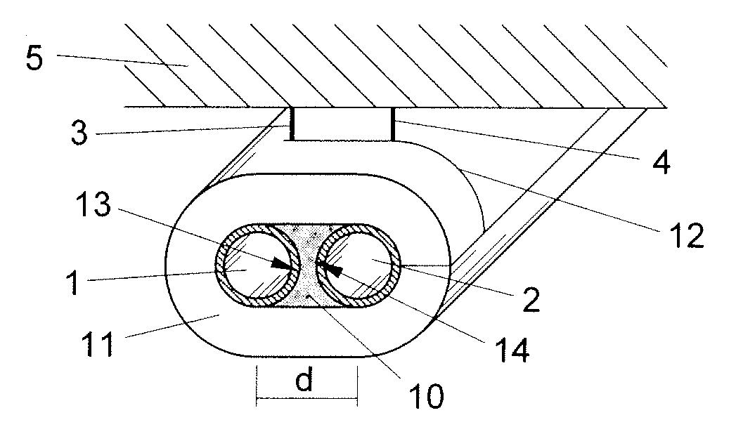
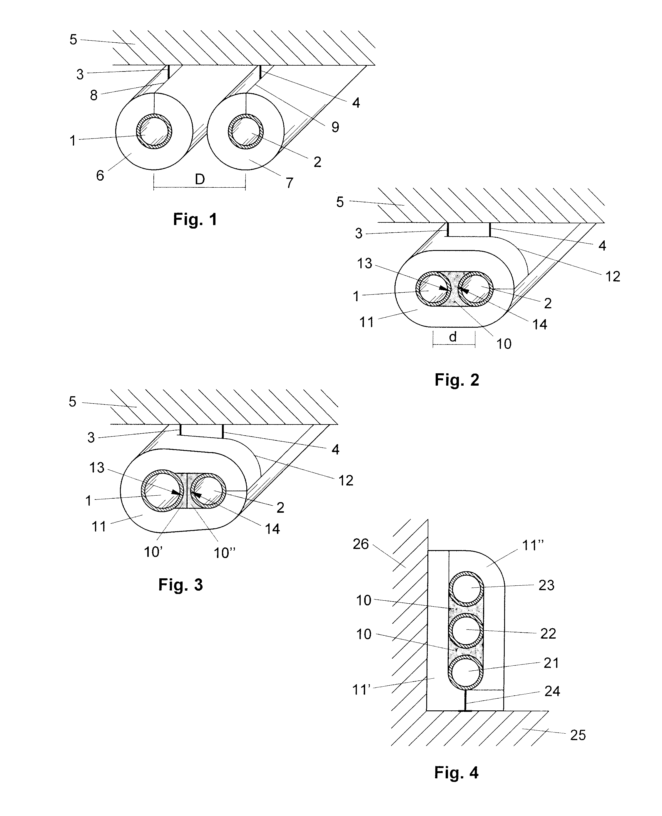
The present invention provides a pipe insulating assembly that allows good heat insulation of pipes that are arranged close to each other without heat exchange between them. The assembly uses two different insulating materials in the form of mineral wool and aerogel, which are placed between the pipes. The insulating materials are arranged in a specific way to achieve good heat insulation, and the assembly can be used in new buildings or for refurbishment purposes. The invention also provides a method for arranging the insulating materials in the pipe assembly. The technical effects of the invention include improved heat insulation, reduced space requirement, and improved fire resistance.

Problems solved by technology

This might be acceptable in some applications, but in most applications it is not acceptable.

Method used


Image

  • Pipe insulating assembly
  • Pipe insulating assembly

Examples


Embodiment Construction

[0032]Many buildings comprise pipes for transferring heating or cooling media. In order to save energy such heating or cooling pipes must be heat insulated so that heat exchange only takes place where it is desired and not in e.g. pipe shafts leading from the heating / cooling installation to the rooms where heating / cooling is needed.

[0033]Conventionally, pipes 1, 2 are mounted by means of pipe hangers or bearings 3, 4 to e.g. a ceiling 5 as shown in FIG. 1. After mounting to the ceiling 5 the pipes 1, 2 are heat insulated individually by means of separate pipe sections 6, 7 provided with a slit 8, 9 so they can be opened and wrapped around the pipes 1, 2. In order to be able to wrap the pipe sections 6, 7 around the pipes 1, 2 they must be separated a certain minimum distance D, which after mounting of the pipe sections 6, 7 leaves an empty space around and between the pipe sections 6, 7.

[0034]By means of the pipe insulating assembly according to the present invention it is possible ...


PUM


Abstract

A pipe insulating assembly for heat insulating at least two substantially parallel pipes (1, 2), which assembly comprises an outer insulating element (11) commonly surrounding the pipes (1, 2). The assembly also comprises an inner insulating element (10) arranged between the pipes (1, 2) and being surrounded by said outer insulating element (11). The inner insulating element (10) has better heat insulating properties than the outer heat insulating element. A method for insulating at least two substantially parallel pipes (1, 2) comprising outer and inner insulating elements is also disclosed.

Description

FIELD OF THE INVENTION[0001]The invention relates to a pipe insulating assembly for heat insulating at least two substantially parallel pipes according to the introduction of claim 1. The invention also relates to a method of heat insulating at least two substantially parallel pipes according to claim 13.BACKGROUND OF THE INVENTION[0002]Products for heat insulating two or more pipes are already known. For instance, DE 201 11 685 A1 shows a pipe section made of polyurethane foam for receiving two parallel pipes. In a first embodiment the pipe section is made as a single unit comprising an elongate body provided with two parallel cylinder-shaped cavities and provided with two slits leading from the outside of the pipe section to each of the two cavities, respectively. In another embodiment the pipe section is made of two pipe sections that are interconnected to form a single unit. In order to exclude any heat exchange between the two pipes they must be separated a certain minimum dist...

Claims


Application Information

Patent Timeline
Patent Type & Authority Applications(United States)
IPC IPC(8): F16L9/14
CPCF16L59/14F16L59/021
Inventor OLSEN, ERLING
Owner ROCKWOOL INT AS
Learn More