

Dividing wall distillation column
- Summary
- Abstract
- Description
- Claims
- Application Information
AI Technical Summary
Benefits of technology
Problems solved by technology
Method used
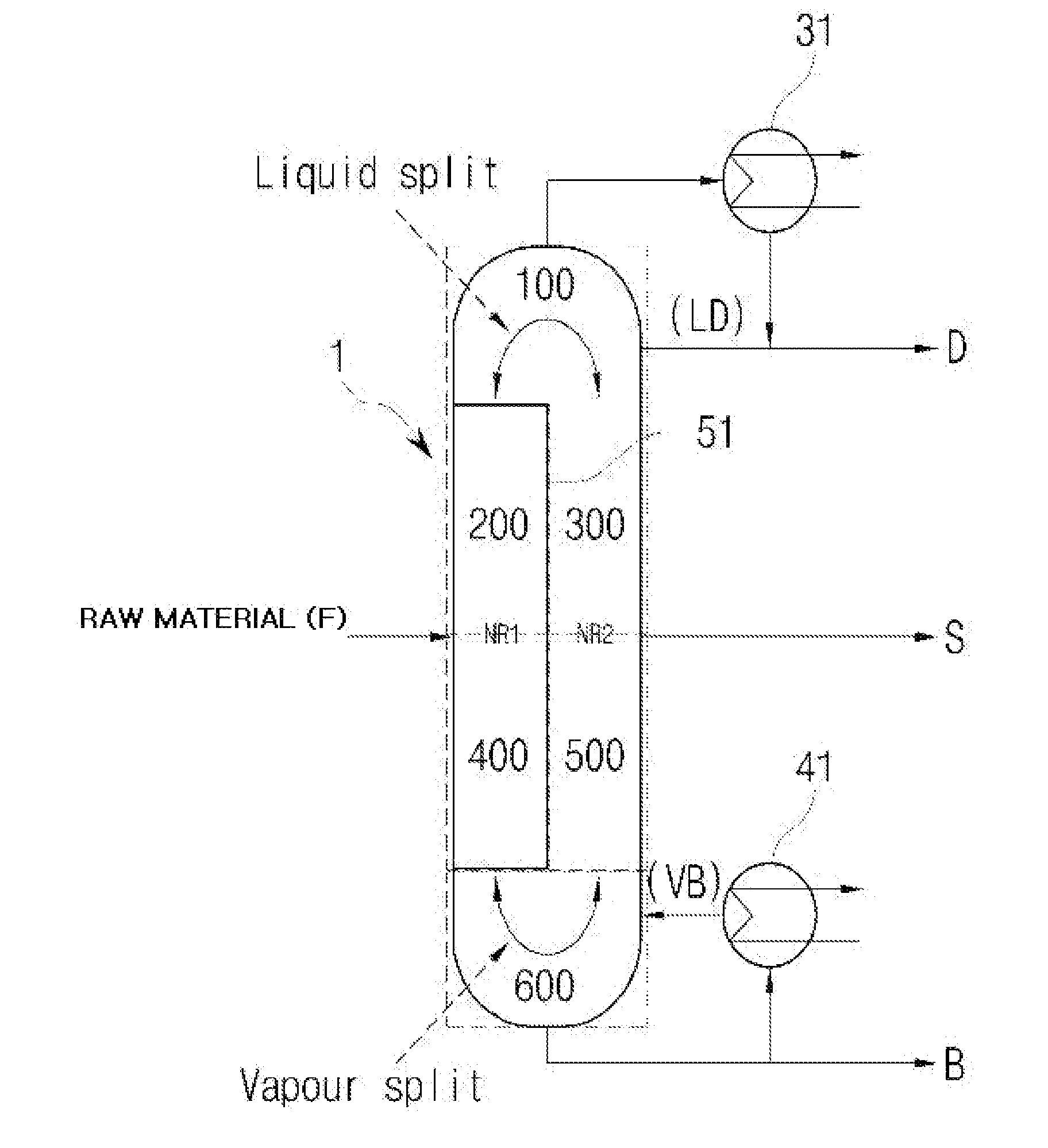
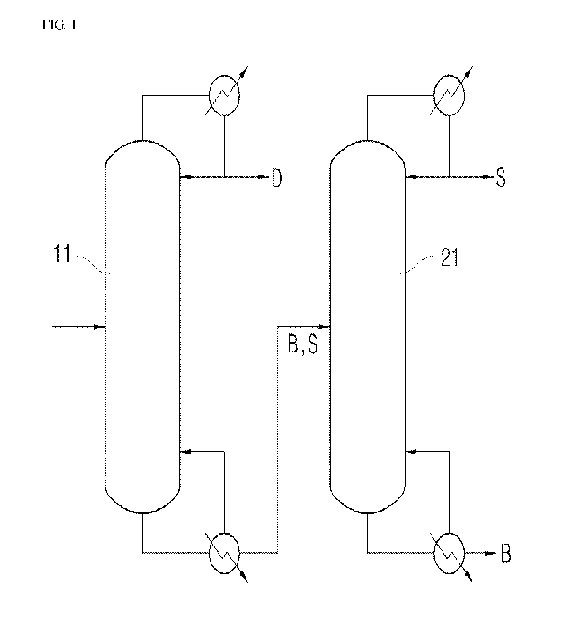
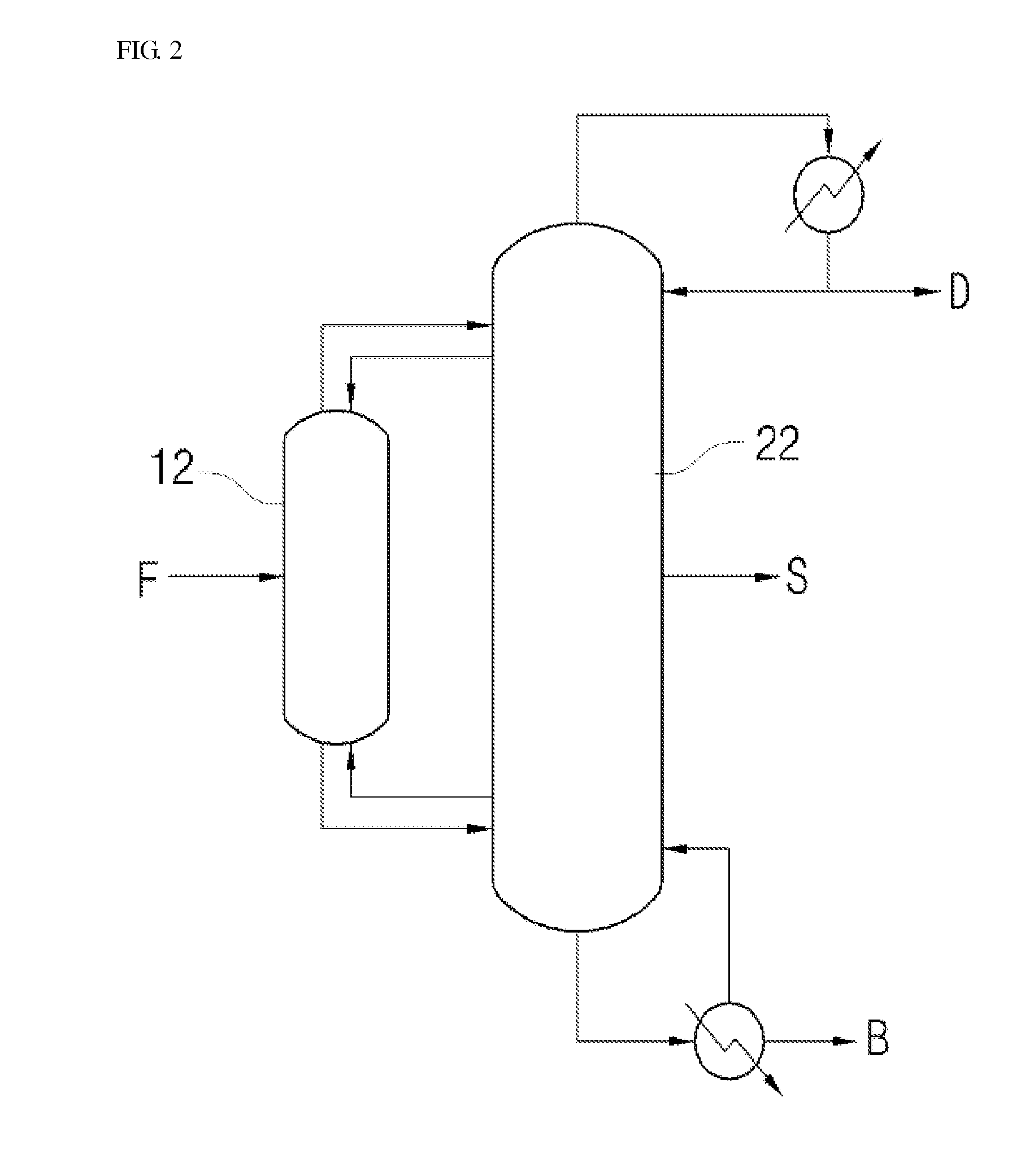
Image

Examples
example 1
[0068]A used packing substance had a specific surface area of 250 m2 / m3 or more and porosity of 0.98 or more, and was made of a metal. A packing column had a height equivalent of a theoretical plate (HETP) of 450 mm or less (a column height is generally calculated as a theoretical plate number and a height equivalent to one theoretical plate). The packing layer was manufactured and installed at a height of 1000 to 7000 mm according to a position and role of the packing layer.
[0069]As shown in FIG. 5, collector trays for regulating pressure drop were installed at the lowermost plate of the upper outflow zone and the uppermost plate of the column-bottom zone (a total of two collector trays). The collector tray for regulating pressure drop had a nozzle size of 25 mm and a rise area of 25% with respect to the sectional area. The two collector trays for regulating pressure drop had the same nozzle size and rise area.
[0070]Also, the dividing wall was designed so that a spacing of the divi...
example 2
[0071]A distillation column was designed and manufactured under the same conditions as in Example 1. However, a collector tray for regulating pressure drop provided in the lowermost plate of the upper outflow zone had a nozzle size of 15 mm and a rise area of 20%, and a collector tray for regulating pressure drop provided in the uppermost plate of the column-bottom zone had a nozzle size of 10 mm and a rise area of 20%.
experimental example 1
Experimental Results on Pressure Drop
[0074]In order to verify the performance of the distillation column proposed in the present invention, the distillation columns designed in Examples 1 and 2 and Comparative Example 1 were operated. When an operational state of the distillation column reached a steady state, a level of the pressure drop was measured. The results are listed in the following Table 1.
TABLE 1ComparativeExample 1Example 1Example 2PreliminaryMainPreliminaryMainPreliminaryMaindivisionaldivisionaldivisionaldivisionaldivisionaldivisionalsectionsectionsectionsectionsectionsectionLiquid0.0590.0120.0590.1120.0590.112distributor onpacking bed#2Packing bed0.1590.5250.1590.5250.1590.525#2Liquid0.1420.1150.1420.1150.1420.115distributor onpacking bed#3Packing bed3.0162.1343.0162.1343.0162.134#3Collector tray———0.112—0.569for regulatingpressure dropLiquid0.1790.1140.1790.1140.1790.114distributor onpacking bed#4Packing bed0.8430.4400.8430.4400.8430.440#4Collector tray0.177—0.1770.11...
PUM
 Abstract
Description
Claims
Application Information