
Sheet guide and image recording apparatus

a technology of image recording apparatus and sheet guide, which is applied in the direction of registering devices, thin material handling, article separation, etc., can solve the problems of increasing the size and cost of the image recording apparatus in which the sheet guide is installed, the difficulty in carrying out the positioning of the sheet, and the increase in the size of the image recording apparatus. , to achieve the effect of ensuring the positioning of each sheet, generating the sliding resistance is extremely simple, and substantially constant sliding resistan

Active Publication Date: 2011-12-22
BROTHER KOGYO KK
View PDF2 Cites 9 Cited by
  • Summary
  • Abstract
  • Description
  • Claims
  • Application Information

AI Technical Summary

Benefits of technology

[0008]Generally, the sliding washer is fastened by a screw together with the pinion. However, by providing such sliding washer, a dimension of the sheet guide (a dimension in a direction of thickness of the pinion) increases, and as a result, leads to an increase in a size of the image recording apparatus in which the sheet guide is installed.
[0010]In view of the abovementioned circumstances, an object of the present teaching is to provide a sheet guide having a simple structure, which is capable of positioning a sheet by a center-register type, and maintaining a state in which the sheet is positioned.
[0014]According to the aspects of the present teaching, since a sliding resistance of the rack is substantially constant, when a user attempts to bring closer the positioning members in pair intentionally, by applying an external force countering the sliding resistance, it is possible to bring the positioning members in pair closer by sliding stably. Similarly, when the user attempts to move away (apart) the positioning members in pair intentionally, by applying an external force countering the sliding resistance, it is possible to move the positioning members in pair away by sliding stably. Consequently, even when the sheets are to be transported continuously, assured positioning of each sheet is achieved. Besides, since the sliding resistance is caused by a frictional force based on a supporting-point reactive force (reaction) which is developed at a site at which the rack and the pinion are engaged, a mechanism for generating the sliding resistance is extremely simple.

Problems solved by technology

However, by providing such sliding washer, a dimension of the sheet guide (a dimension in a direction of thickness of the pinion) increases, and as a result, leads to an increase in a size of the image recording apparatus in which the sheet guide is installed.
Therefore, when there is an extreme increase or decrease in the sliding resistance, there is a problem of having a difficulty in carrying out positioning of a sheet.
However, when such a mechanism is provided, it will lead to further increase in size and cost of the image recording apparatus.

Method used


Image

  • Sheet guide and image recording apparatus
  • Sheet guide and image recording apparatus
  • Sheet guide and image recording apparatus

Examples


first embodiment

[0027][Outline of copy machine]

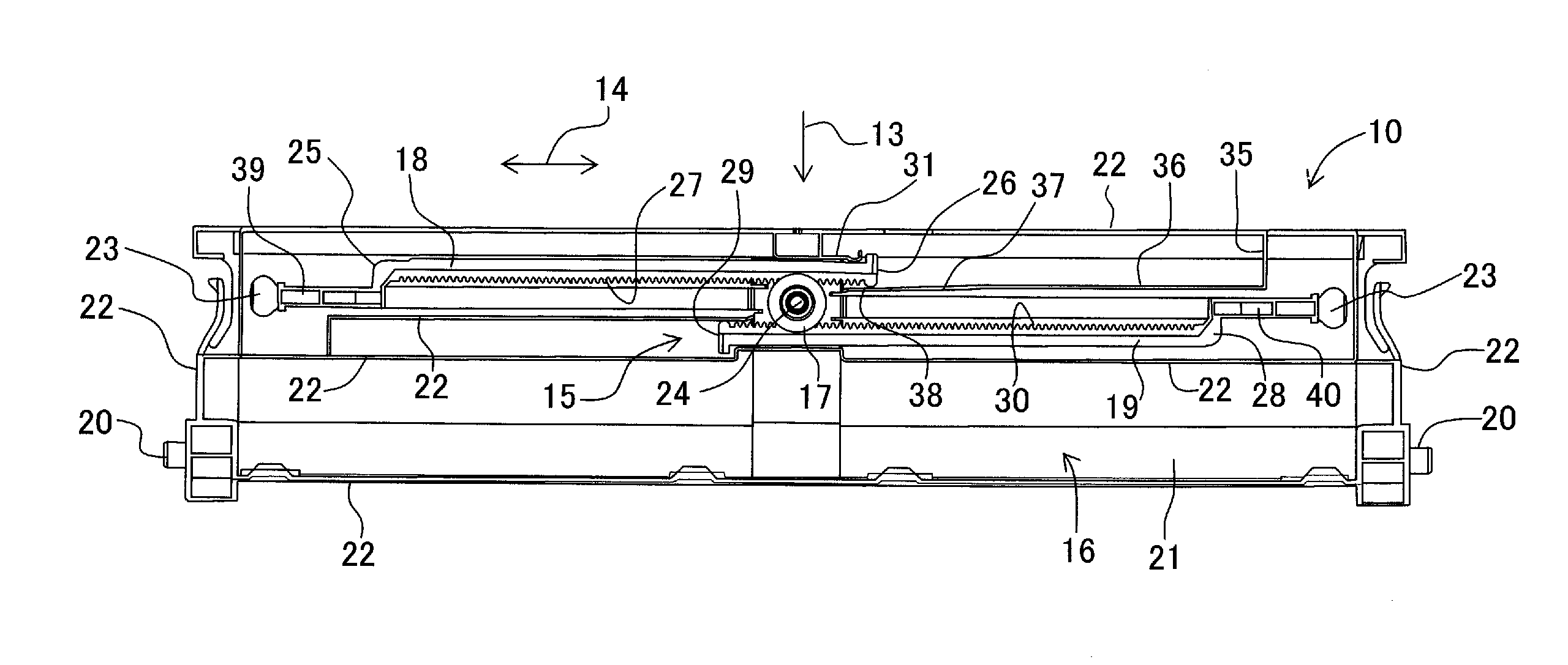
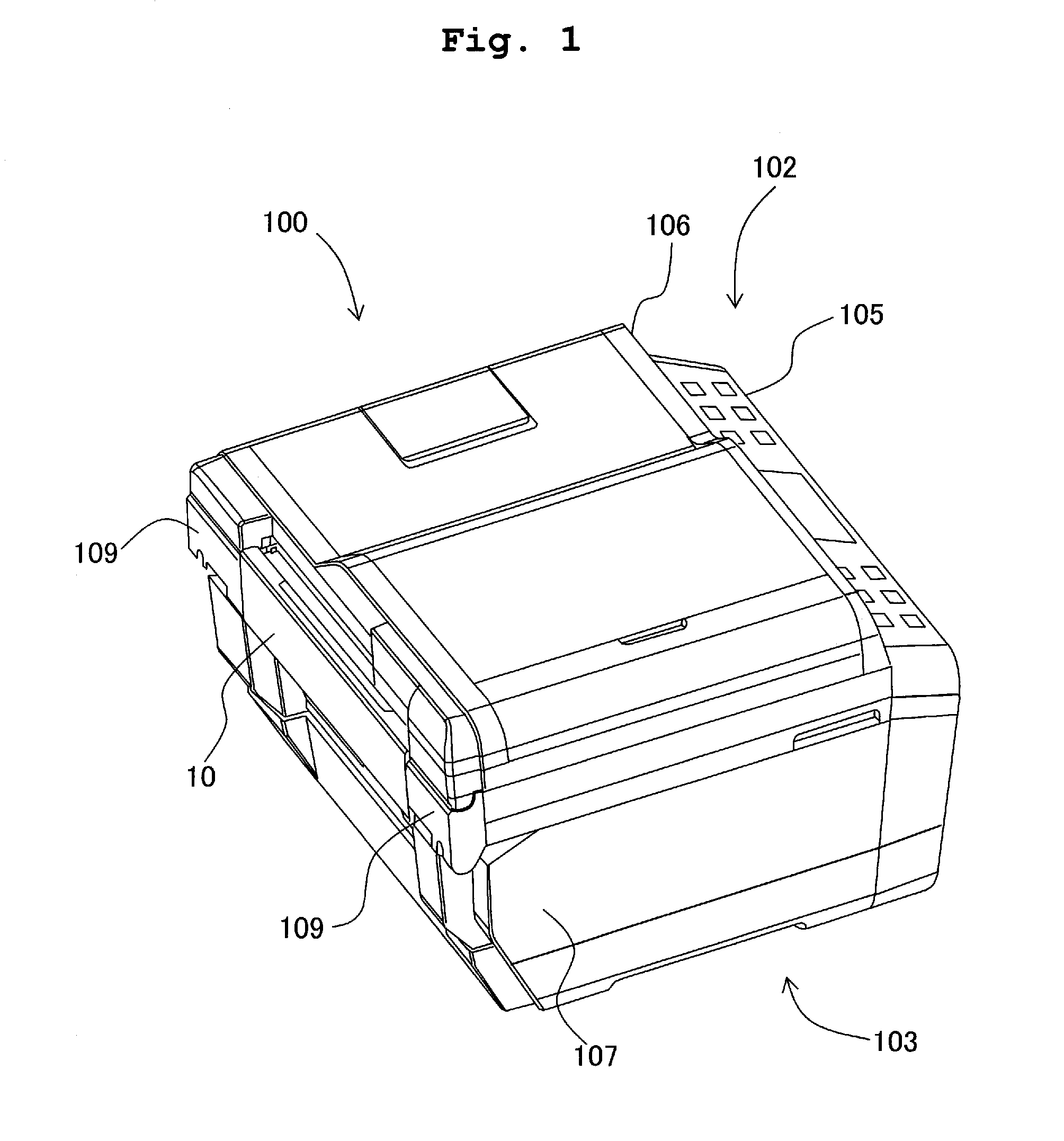
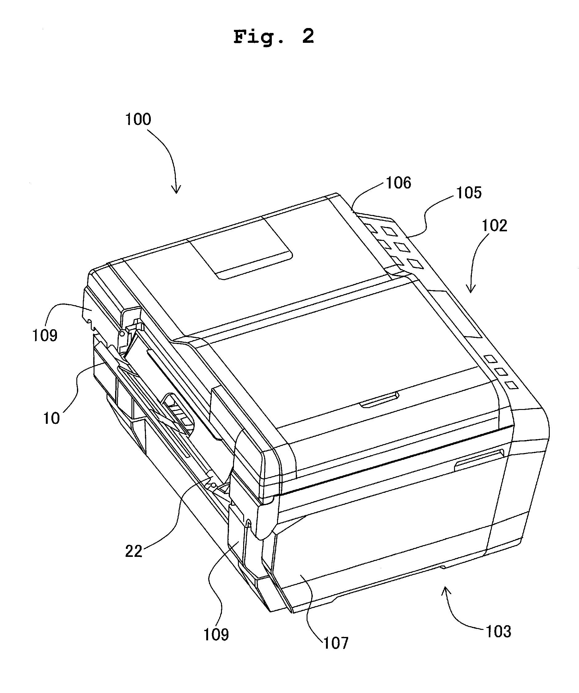
[0028]As shown in FIG. 1 and FIG. 2, a copy machine 100 includes an image reading section 102 at an upper portion, and a printer section 103 (corresponds to ‘an image recording apparatus’ of the first embodiment) of an ink-jet recording type at a lower portion. The copy machine 100 has various functions such as a facsimile function, a printer function, a scanner function, and a copy function. A transporting path 101, which will be described later, is formed in the printer section 103, and a sheet (typically a recording paper) is transported along the transporting path 101. A recording section 112 (refer to FIG. 3) is arranged in the transporting path 101, and the recording section 112 records an image on the sheet which is transported along the transporting path 101. A peculiarity (characteristic) of the first embodiment is a point that a sheet guide 10 which will be described later is provided at an upstream side of the transporting path 101. The shee...

first modified embodiment

of First Embodiment

[0063]A point at which a sheet guide 70 according to a first modified embodiment of the first embodiment differs from the sheet guide 10 according to the first embodiment is that, in the sheet guide 70, a supporting plate 71 is not extended up to the pinion 17, and is cut off in between. As shown in FIG. 7A and FIG. 7B, an end portion 72 (corresponds to an ‘end portion toward the pinion’ or an ‘end portion facing the pinion’ in the first modified embodiment of the first embodiment) of the supporting plate 71, facing the pinion 17 is separated apart from the pinion 17 by a fixed (constant) distance in the sliding direction 14. In this modified embodiment, as shown in FIG. 7B, the supporting plate 71 does not face the pressing arm 31. The rest of the structure is similar to the structure of the sheet guide 10.

[0064]As it has been mentioned above, with the span S1 becoming smaller, the supporting-point reactive force Rb increases. However, since the end portion 72 of...

second modified embodiment

of First Embodiment

[0066]A point at which, a sheet guide 50 according to a second modified embodiment of the first embodiment differs from the sheet guide 10 according to the first embodiment is that, a rear surface 51 of the rack 18 is inclined. The rest of the structure is similar to the structure of the sheet guide 10.

[0067]As shown in FIG. 8A and FIG. 8B, the rear surface 51 of the rack 18 is a surface with which, the pressing arm 31 makes a contact, and is a surface being pressed against by the pressing arm 31. Moreover, the rear surface 51 is inclined in a direction of separating apart from the pinion 17, or in other words, a direction opposite to a direction in which, the pressing arm 31 presses the rack 18, with respect to the sliding direction 14, directed from the other end portion 26 of the rack 18 toward the one end portion 39. In other words, the rear surface 51, as coming closer to the other end portion 26, is inclined toward the pressing direction with respect to the ...


PUM


Abstract

A sheet guide includes a base on which a sheet is placed; a pinion which is rotatably provided on the base; a pair of racks which are extended in a sliding direction, which sandwich the pinion therebetween, which are engaged with the pinion to move opposite to each other in the sliding direction; a pair of positioning members which are provided at one end portions of the pair of racks respectively, and which come closer and move away from each other by movement of the pair of racks to position the sheet in the sliding direction; a sliding guide which is formed in the base and which guides the pair of racks in the sliding direction; and a pressing member which is provided on the base and which presses a portion of at least one rack of the racks to urge the at least one rack against the pinion.

Description

CROSS REFERENCE TO RELATED APPLICATION[0001]The present application claims priority from Japanese Patent Application No. 2010-138668, filed on Jun. 17, 2010, the disclosure of which is incorporated herein by reference in its entirety.BACKGROUND OF THE INVENTION[0002]1. Field of the Invention[0003]The present invention relates to a sheet guide and an image recording apparatus. For instance, at the time of transporting a sheet such as a recording paper, there is a structure of a sheet guide which positions the sheet in a direction intersecting a transporting direction. Such sheet guide is typically used in an automatic document feeder installed in an image recording apparatus, and other document trays and a paper feeding tray which supports the recording paper.[0004]2. Description of the Related Art[0005]An image recording apparatus such as a copy machine and a printer includes a tray on which a plurality of sheets (basically, documents and recording papers) is piled up. Sheets placed...

Claims


Application Information

Patent Timeline
IPC IPC(8): B65H9/04
CPCB65H3/44B65H9/04B65H2403/411B65H2405/324B65H2407/21B65H1/00B65H2801/06B65H2511/12B65H2220/01B65H2220/04B65H2511/22B65H2220/11
Inventor UCHINO, YUTA
Owner BROTHER KOGYO KK
Learn More