
Automatically commissioning of devices of a networked control system

a networked control system and automatic commissioning technology, applied in the direction of digital computer details, lighting and heating apparatus, instruments, etc., can solve the problems of cumbersome and error-prone operation, and achieve the effect of avoiding unnecessary routing of commissioning messages through the grid and avoiding loss of commissioning messages due to a faulty nod

Inactive Publication Date: 2011-12-22
KONINKLIJKE PHILIPS ELECTRONICS NV
View PDF1 Cites 36 Cited by
  • Summary
  • Abstract
  • Description
  • Claims
  • Application Information

AI Technical Summary

Benefits of technology

[0015]Furthermore, the act of updating of the hops counter by the second device may comprise comparing the hops counter of the received commissioning message with the actual location counter of the second device and incrementing the hops counter by one only if the comparing results in that the hops counter is larger than or equal to the actual location counter of the second device. This allows avoiding problems with faulty devices, which usually do not route and update received commissioning messages. A faulty device may cause the start and stop of commissioning messages, which should only start and stop at end devices in the grid. Commissioning messages being started in the neighborhood of faulty devices may however cause commissioning messages with incorrect hops counters. With the comparison of the hops counter of a received commissioning message with the actual location counter, an incorrect update of the hops counter and the location counter of a device may thus be avoided.
[0016]The act of updating of the hops counter by the second device may further comprise rejecting the received commissioning message if the comparison results in that the hops counter is smaller than the actual location counter of the second device. This allows keeping the number of commissioning messages small and the data traffic due to the routing of commissioning messages low, because unnecessary routing of commissioning messages through the grid is avoided.
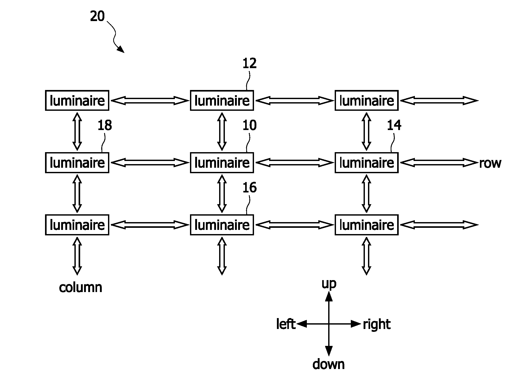
[0017]The transmitting of the commissioning message with the updated hops counter to one or more third devices may comprise transmitting the commissioning message with the updated hops counter to a third device, which is neighbored to the second device in the predetermined direction in the grid, or to third devices, which are neighbored to the second device in the predetermined direction in the grid and in two further different directions, each being different from the predetermined direction. The latter method allows routing of commissioning messages through the grid not only in one predetermined direction, for example in the up direction, but also in other directions, for example in the left and right direction. Thus, faulty devices may be circumvented, and a loss of a commissioning message due to a faulty node may be avoided. Furthermore, the location counters of devices neighbored to a faulty device may be checked whether they are correct, and eventually updated in order to be correct.
[0019]A third device, which is neighbored to the second device in a direction different from the predetermined direction, may also transmit a commissioning message in the predetermined direction in the grid and in the two further different directions, each being different from the predetermined direction. Thus, a commissioning message may be routed on not only in the predetermined direction, but also in the other different directions. This allows routing of a commissioning message on a flexible way though the grid and to improve the commissioning since also clusters of faulty devices may be circumvented.

Problems solved by technology

This process, often referred to as commissioning, is a cumbersome and error prone operation.

Method used


Image

  • Automatically commissioning of devices of a networked control system
  • Automatically commissioning of devices of a networked control system
  • Automatically commissioning of devices of a networked control system

Examples


Embodiment Construction

[0053]In the following, functionally similar or identical elements may have the same reference numerals. Even if embodiments of the invention, which are described in the following, relate to lighting systems, the invention is generally applicable to networked control systems, which comprise several devices to be commissioned.

[0054]In professional environments it becomes more and more interesting to control lights on an individual and local basis. Examples of such environments are green houses, factory buildings, sport halls, office buildings and outdoor (matrix) light displays. Instead of switching on or off all luminaries, it is preferred to control single luminaries or groups of luminaries in order to locally create light effects in certain areas, for example in order to illuminate certain areas in an office building or to create light for only some plants in a certain place in a green house. Also, often it is required to individually control luminaries of a lighting system with f...


PUM


Abstract

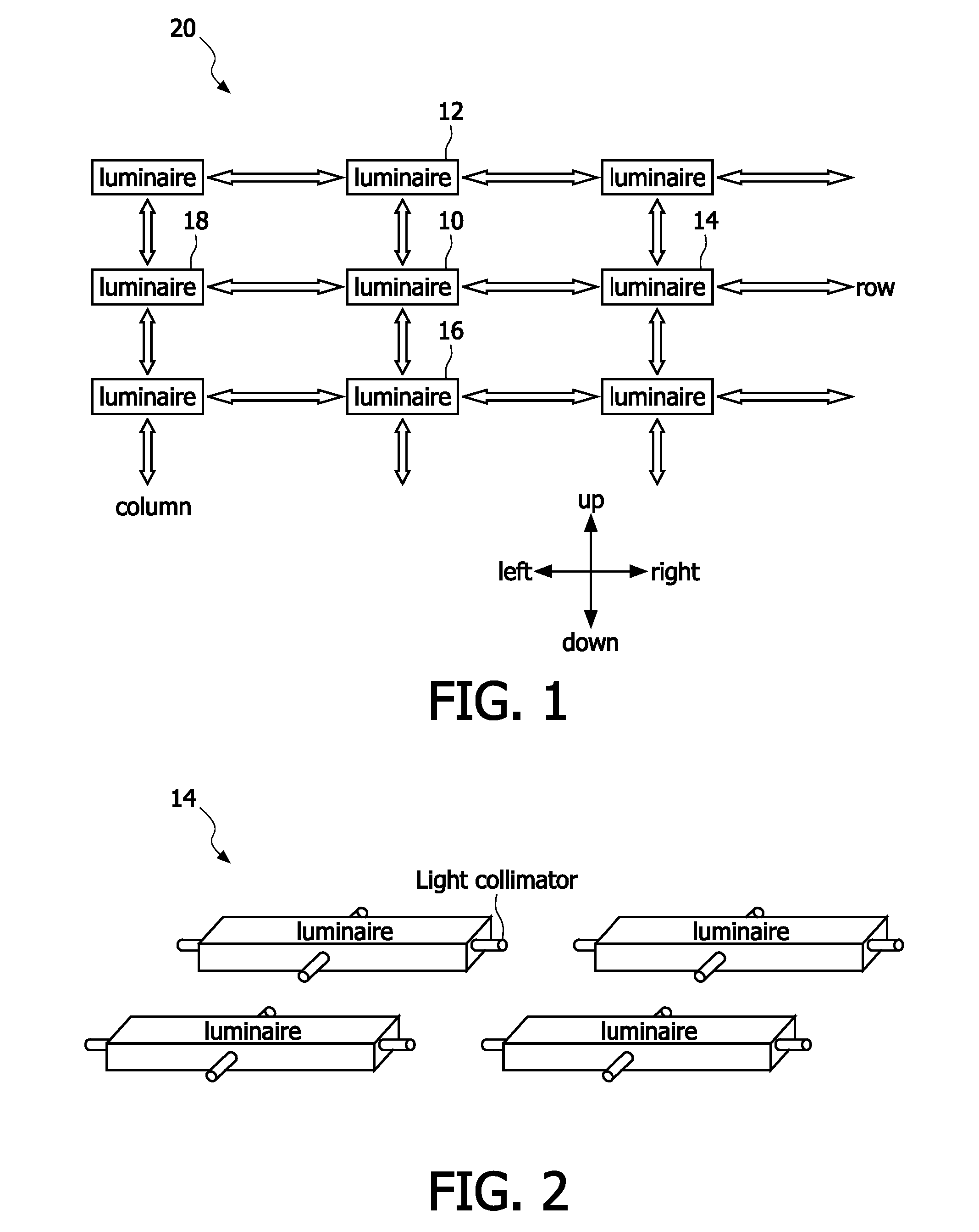
The invention relates to automatically commissioning of devices of a networked control system, particularly to automatically commissioning (auto-commissioning) of light sources of a lighting system, where a control of light sources on an individual and local basis is required. A basic idea of the invention is to route commissioning messages through a grid, particularly an approximately rectangular grid of devices in that each device is able to receive commissioning messages from and to transmit commissioning messages to directly neighbored devices in the grid via light. An embodiment of the invention relates to a method for automatically commissioning of devices (10, 12, 14, 16, 18) of a networked control system, which comprises several devices arranged in a grid (20), wherein each device is adapted for routing messages, which were received from directly neighbored devices in the grid, to directly neighbored devices in the grid via light, wherein the commissioning comprises the acts oftransmitting a commissioning message (S10), which comprises a hops counter, by a first device (10) to a second device (12), which is neighbored to the first device in a predetermined direction (22) in the grid,receiving the commissioning message (S12) from the first device by the second device,updating the hops counter (S14) by the second device and a location counter of the second device andtransmitting the commissioning message (S16) with the updated hops counter to one or more third devices.

Description

FIELD OF THE INVENTION[0001]The invention relates to automatically commissioning of devices of a networked control system, particularly to automatically commissioning of light sources of a lighting system, where a control of light sources on an individual and local basis is required.BACKGROUND OF THE INVENTION[0002]Networked control systems are a ubiquitous trend in commercial, industrial and institutional business markets and also in consumer markets. An example of a networked control system is a complex lighting system with dozens of light sources. Particularly, in professional environments it becomes more and more interesting to control lights on an individual and local basis. Examples of such environments are green houses, factory buildings, sport halls, office buildings and outdoor (matrix) light displays. Messages to control individual lights can be centrally generated, e.g. for the outdoor (matrix) light display, but might also be based on local sensor findings, e.g. for gree...

Claims


Application Information

Patent Timeline
Patent Type & Authority Applications(United States)
IPC IPC(8): G06F15/173F21V5/04
CPCH05B37/0272H05B37/0254H05B47/18H05B47/195H05B47/199H05B47/19
Inventor VAN DER STOK, PETRUS DESIDERIUS VICTORFERI, LORENZOPASVEER, WILLEM FRANKESCHENK, TIM CORNEEL WILHELMUS
Owner KONINKLIJKE PHILIPS ELECTRONICS NV
Learn More