Thermally assisted head having reflection mirror for propagating light

a technology of mirror and magnetic head, applied in special recording techniques, instruments, record information storage, etc., can solve the problems of difficult to record information with a conventional magnetic head, obstacle to achieving an increase in recording density, and disadvantages of conventional magnetic recording, etc., to achieve the effect of suppressing plasmon generation

Active Publication Date: 2011-12-22
TDK CORPARATION
View PDF3 Cites 9 Cited by
  • Summary
  • Abstract
  • Description
  • Claims
  • Application Information

AI Technical Summary

Benefits of technology

[0019]A magnetic head of the present invention includes a magnetic head slider; and a laser diode that is positioned on a surface of a side opposite to a substrate of the magnetic head slider and that generates laser light; the magnetic head slider including: a core through which the laser light emitted from the laser diode propagates as propagating light; a cladding that covers the core and that has a refractive index that is smaller than that of the core; a near field light generating means that generates near field light from the propagating light on an air bearing surface; and a

Problems solved by technology

As a result, it becomes difficult to record information with a conventional magnetic head.
Conventional magnetic recording has such a drawback, and this is a large obstacle to achieving an increase in the recording density.
Ordinary light cannot be focused to a region that is smaller than its wavelength due to diffraction limitations.
However, with this method, a conversion efficiency to convert irradiated light into the near field light is low.
As a result, a problem in which servo signals recorded on the magnetic recording medium are barely sensed during the recording proc

Method used


Image

  • Thermally assisted head having reflection mirror for propagating light
  • Thermally assisted head having reflection mirror for propagating light
  • Thermally assisted head having reflection mirror for propagating light

Examples


Embodiment Construction

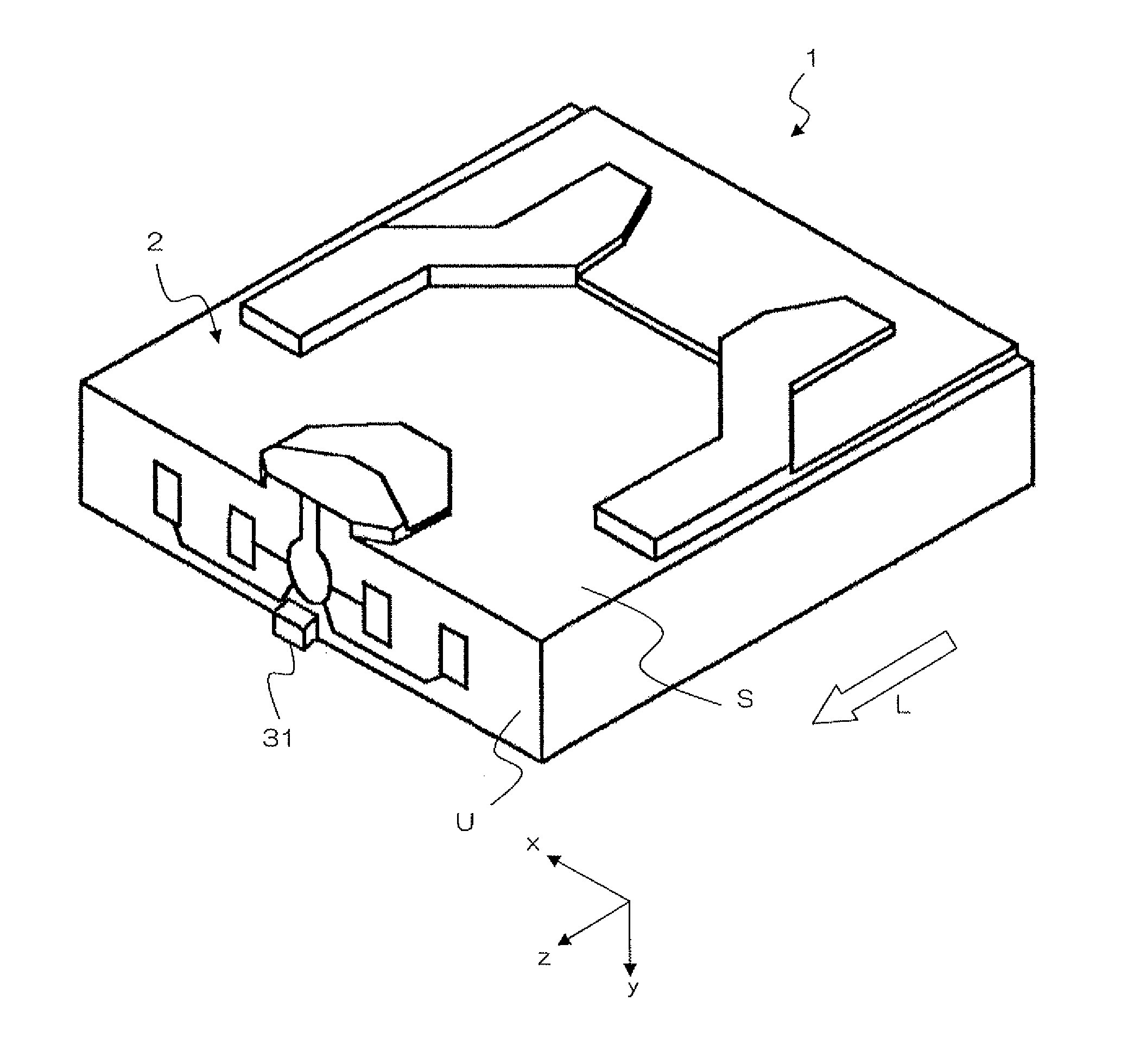
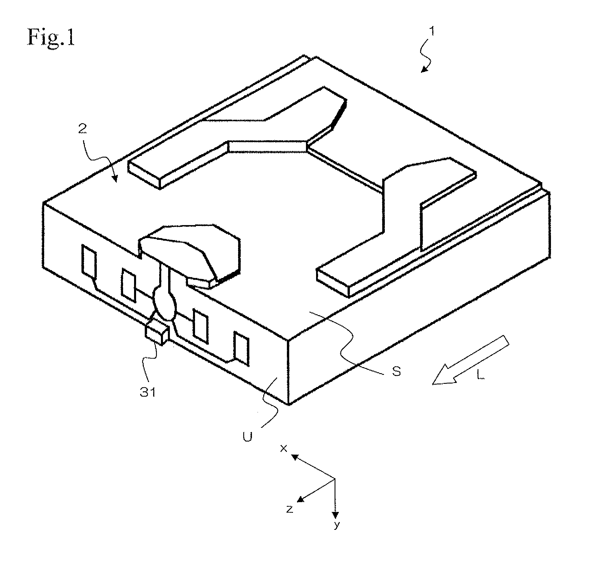
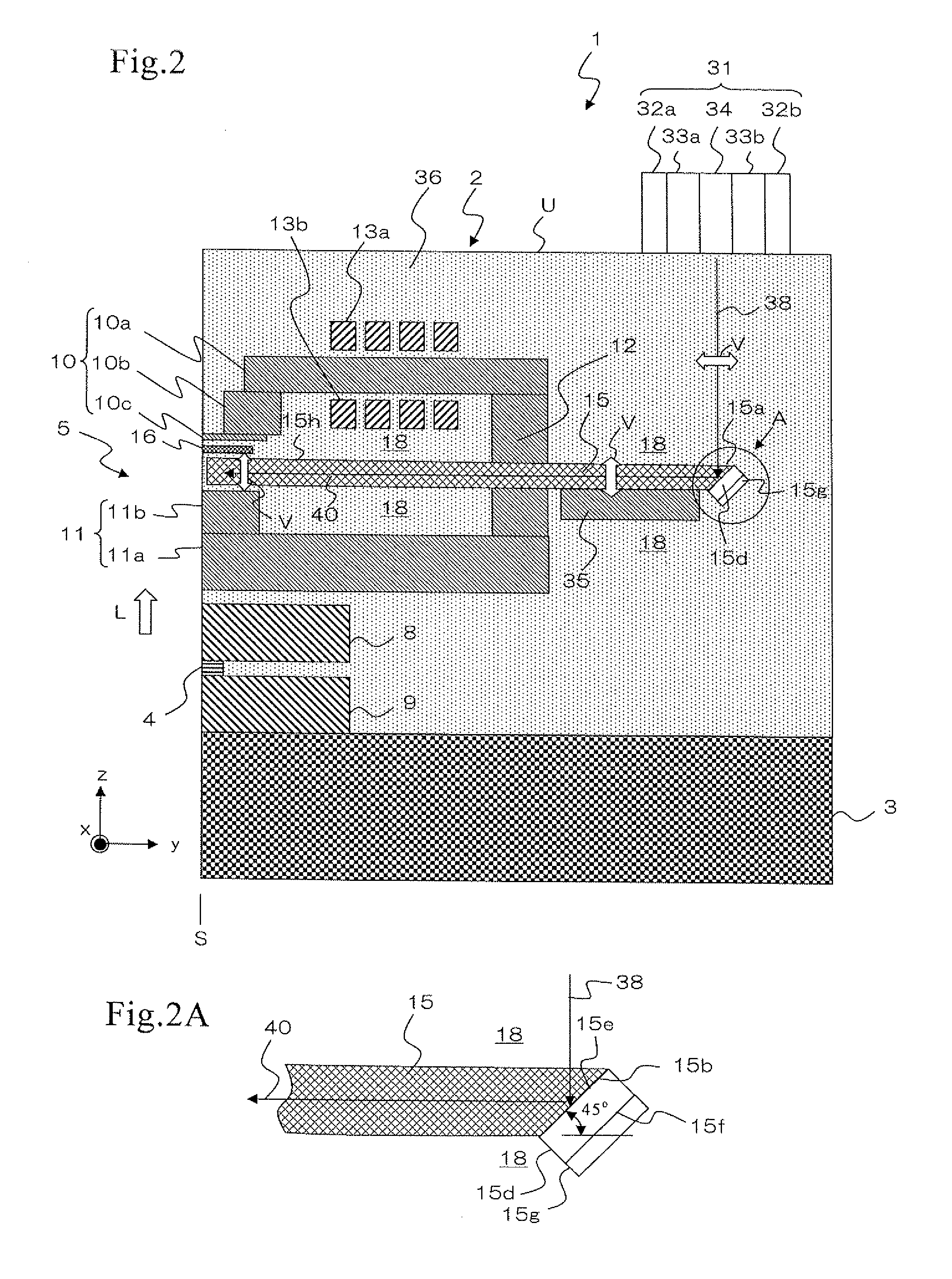
[0035]A magnetic head of the present invention will be explained referring to the drawings. FIG. 1 is an entire perspective view of the magnetic head according to one embodiment of the present invention. FIG. 2 is a cross-sectional view of a main part of the magnetic head. In this specification, a lamination direction L means a film formation direction in a wafer process and corresponds to the z-direction in each of the drawings. “Upward lamination direction” means a direction oriented toward an overcoat layer 36 from a substrate 3, and “downward lamination direction” means a direction oriented toward the substrate 3 from the overcoat layer 36.

[0036]A magnetic head 1 includes a magnetic head slider 2 and a laser diode 31. The laser diode 31 is firmly attached to the magnetic head slider 2 and generates laser light. The magnetic head slider 2 has an approximately hexahedral shape, and one surface of the six outer surfaces is an air bearing surface S facing a magnetic recording medium...


PUM


Abstract

A magnetic head includes a magnetic head slider; and a laser diode that is positioned on a surface of a side opposite to a substrate of the magnetic head slider and that generates laser light; the magnetic head slider including: a core through which the laser light emitted from the laser diode propagates as propagating light; a cladding that covers the core and that has a refractive index that is smaller than that of the core; a near field light generating means that generates near field light from the propagating light on an air bearing surface; and a main pole for recording that is disposed adjacent to the near field light generating means and of which an edge part is positioned on the air bearing surface. The core includes a reflection layer and a seed layer, the reflection layer has a refractive index smaller than that of the core, and has a reflection surface on which laser light emitted from the laser diode reflects so as to enter the core as the propagating light, and the seed layer is positioned on a back surface of the reflection surface of the reflection layer and suppresses plasmon generation on the reflection surface.

Description

BACKGROUND OF THE INVENTION[0001]1. Field of the Invention[0002]The present invention relates to a thermally-assisted type magnetic head.[0003]2. Description of the Related Art[0004]In recent years, in association with the high recording density of magnetic recording devices such as hard disk devices, there has been a demand for improvement in the performance of thin film magnetic heads and magnetic recording media. Composite-type thin film magnetic heads have been widely used for the thin film magnetic head. The composite-type thin film magnetic head includes a reproducing head having a magneto resistive effect element (hereafter, referred to as an MR element) for reading and a recording head having an inductive electromagnetic transducer (a magnetic recording element) for writing, with both heads being laminated on a substrate. The thin film magnetic head incorporated in the hard disk device flies just above a surface of the magnetic recording medium during recording and reproduci...

Claims


Application Information

Patent Timeline
IPC IPC(8): G11B11/00G11B5/48
CPCG11B5/314G11B2005/0021G11B2005/001G11B5/6088
Inventor KOMURA, EIJICHOU, TSUTOMUSHIMAZAWA, KOJI
Owner TDK CORPARATION
Why Eureka
Try Eureka