Image recording apparatus

a recording apparatus and image technology, applied in the direction of thin material processing, article separation, printing, etc., can solve the problems of not only causing but also a position shift in the transporting direction, and it is not possible to prevent the position shift of the recording medium. to achieve the effect of reducing or suppressing the second roller

Active Publication Date: 2011-12-22
BROTHER KOGYO KK
View PDF2 Cites 44 Cited by
  • Summary
  • Abstract
  • Description
  • Claims
  • Application Information

AI Technical Summary

Benefits of technology

[0023]In the present invention, even when the force in the transporting direction is exerted due to the load exerted by the load member being ceased to be exerted, the force is counterbalanced by the force exerted to the second roller in the opposite direction o...

Problems solved by technology

However, when the roller is rotatably supported at two ends in the axial direction, there is a possibility of not only bending of the roller but also ...

Method used


Image

  • Image recording apparatus
  • Image recording apparatus
  • Image recording apparatus

Examples


modified embodiment

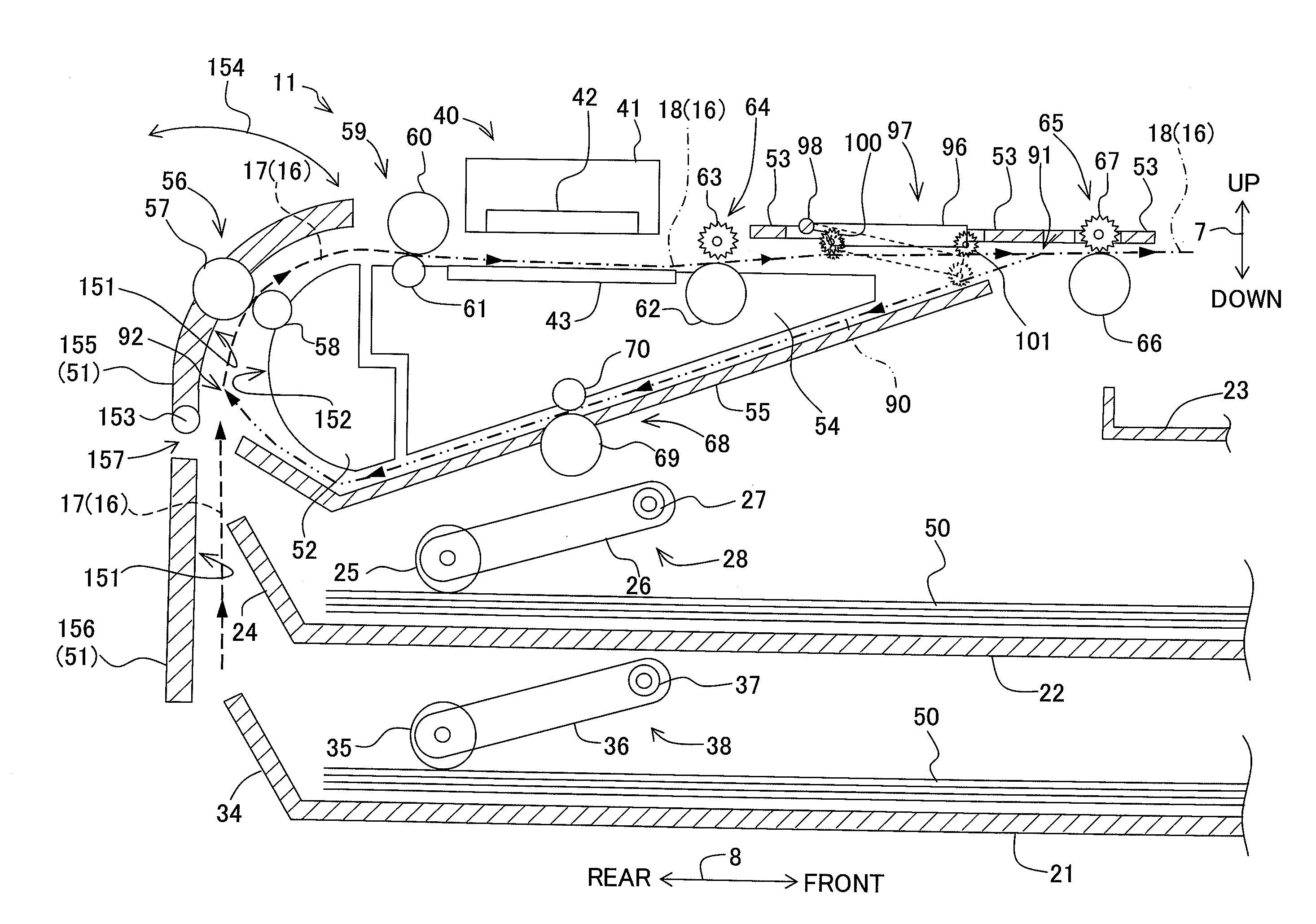
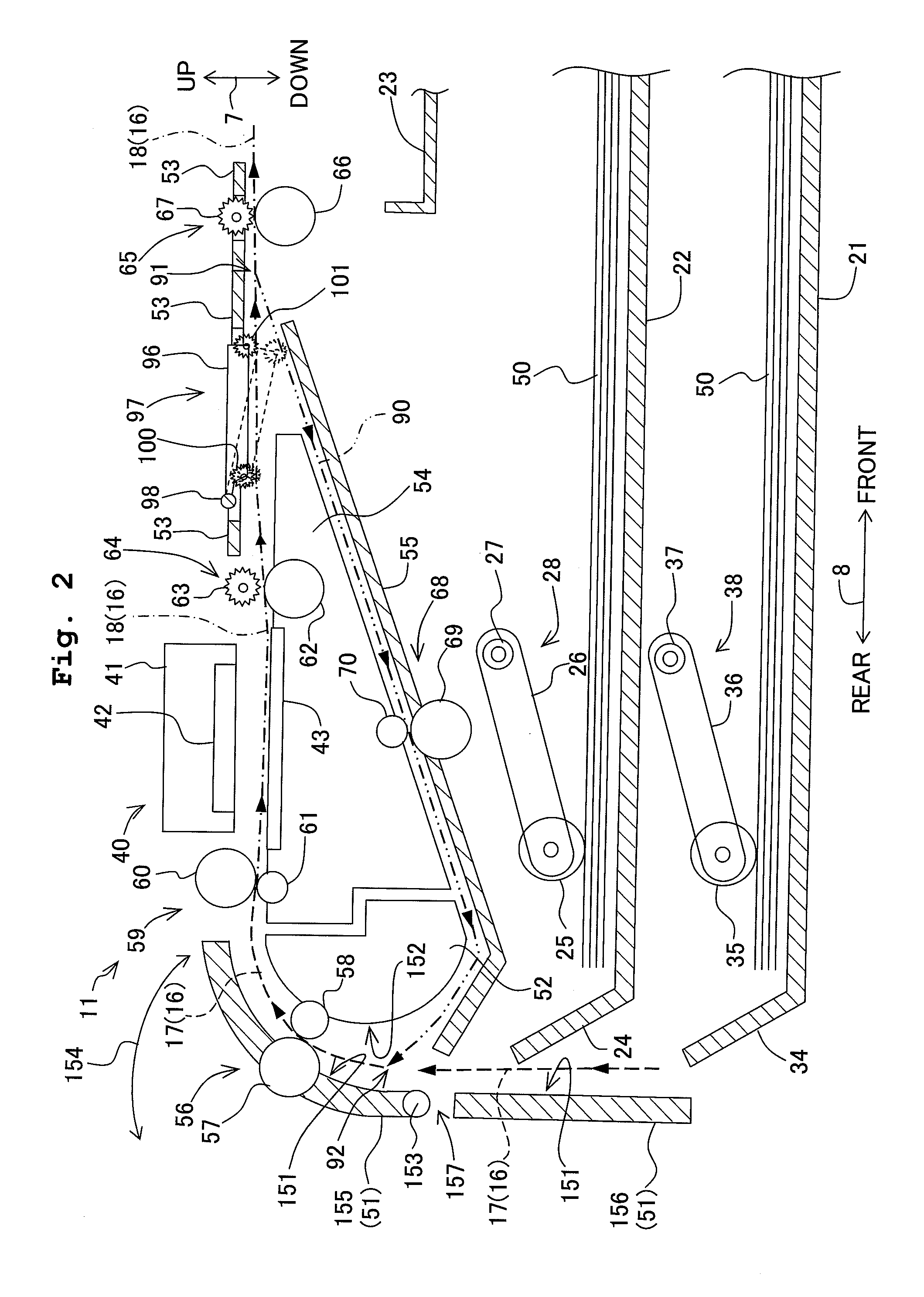
[0076]In the abovementioned embodiment, an arrangement in which the transporting roller 60 is arranged at the upper side of the first transporting path 16, and the pinch roller 61 is arranged at the lower side of the first transporting path 16 has been described. However, the present teaching is not restricted to such an arrangement. For instance, an arrangement may be made to be such that, the transporting roller 60 is arranged at the lower side of the first transporting path 16, and the pinch roller 61 is arranged at the upper side of the first transporting path 16. In this case, the holding member 80 is formed to be vertically symmetrical with respect to the above-mentioned embodiment, and makes a sliding contact with the transporting roller 60 which has been arranged at the lower side of the first transporting path 16.


PUM


Abstract

There is provided an image recording apparatus including a transporting path, a recording section, a first and second rollers pinching the recording medium therebetween, a supporting member which rotatably supports the second roller, a holding member which is movable along a transporting direction of the recording medium, a bias applying member which applies a bias on the holding member, in an opposite direction opposite to the transporting direction and a load member which generates a load in the opposite direction, with respect to the recording medium.

Description

CROSS REFERENCE TO RELATED APPLICATION[0001]The present application claims priority from Japanese Patent Application No. 2010-137919, filed on Jun. 17, 2010, the disclosure of which is incorporated herein by reference in its entirety.BACKGROUND OF THE INVENTION[0002]1. Field of the Invention[0003]The present invention relates to an image recording apparatus which transports a recording medium along a transporting path, and records an image on the recording medium.[0004]2. Description of the Related Art[0005]In an image recording apparatus, in many cases, transporting of a recording medium such as a recording paper is carried out by a pair of rollers (a roller pair). The pair of rollers includes a drive roller which rotates when a driving force from a drive source is transmitted, and a driven roller which rotates with the rotation of the drive roller, and the recording medium is pinched by the rotating roller pair and is transported by the roller pair.[0006]The rollers included in th...

Claims


Application Information

Patent Timeline
IPC IPC(8): B41J11/04
CPCB41J13/025B65H5/062B65H2402/31B41J11/04B65H2404/174B41J13/03B65H2402/5152B65H2402/51B65H2404/1521
Inventor KAWAMATA, NORIYUKIKOGA, YUJISUGIYAMA, WATARUSAMOTO, KENJI
Owner BROTHER KOGYO KK
Why Eureka
Try Eureka