Surgical guiding device for reconstruction of anterior cruciate ligament

Inactive Publication Date: 2011-12-22
RICHARD WOLF GMBH
View PDF9 Cites 47 Cited by
  • Summary
  • Abstract
  • Description
  • Claims
  • Application Information

AI Technical Summary

Benefits of technology

[0025]In particular, this enables the predetermined width of the bone to be maintained easily at all times, even for different drillhole diameters. The width of this bone bridge may be defined in advance by sliding the mounting along the guide arm relative to the position of the fixing device. With larger drillhole diameters, the mounting is moved correspondingly farther away from the fixing device, so that the angle between the axes, along which the alignment wires are introduced into the bone, becomes larger. This also has the effect of increasing the distance between the center axes of the drillholes on the exit side of the bone, so that the distance between the outer sides of the drillholes, that is, the width of the bone bridge, may be kept constant.
[0026]In order to make it easier for the surgeon to position the mounting correspondingly, markings may be applied to the guide arm, indicating predetermined positions for the mounting at a distance from the fixing device. Thus, at least one second predetermined position for the mounting is characterized with a marking preferably at a distance from the fixing device on the guide arm, wherein the marking is positioned such that a predetermined width of the bone bridge is maintained between the drillholes when a first drillhole is inserted at the position of the fixing device and a second drillhole at the position of the marking taking into account the drillhole diameter. This makes it considerably easier to drill the holes.
[0027]After the guide hook is set, initially a first alignment wire is introduced into the bone via the mounting when the mounting is at the position of the fixing device. The wire is then fixed on the fixing device and the mounting is moved to the position of the marking on the guide arm. Then, a second alignment wire is inserted in the bone through the mounting. In this case, the preset marking ensures that the alignme

Problems solved by technology

However, it is only possible to make one targeted drillhole in the bone using these guiding devices, so the instrument is not suitable for use in double-bundle reconstruction.
The drawback with this guiding device is that the bone bridge between t

Method used


Image

  • Surgical guiding device for reconstruction of anterior cruciate ligament
  • Surgical guiding device for reconstruction of anterior cruciate ligament
  • Surgical guiding device for reconstruction of anterior cruciate ligament

Examples


Embodiment Construction

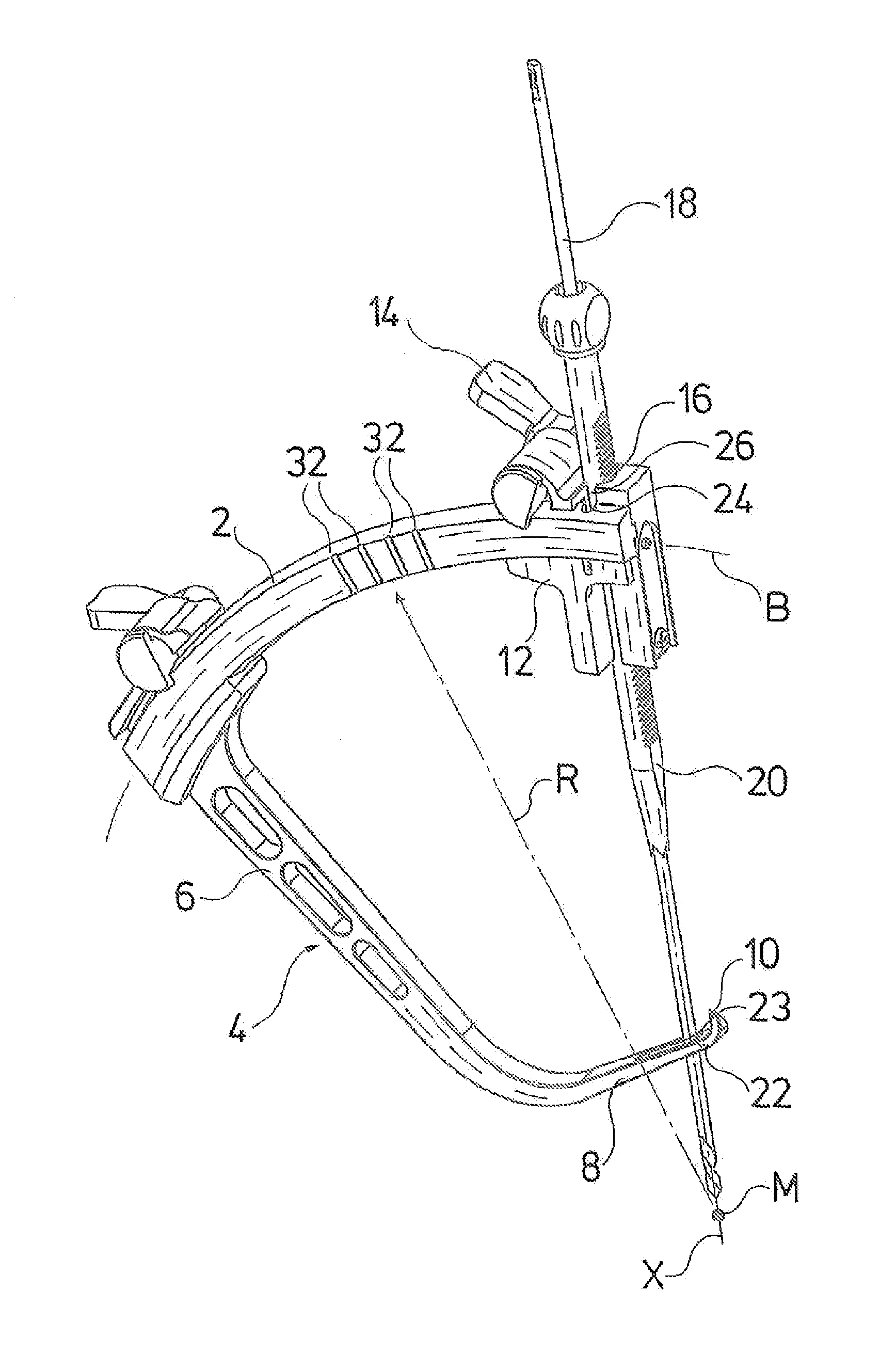
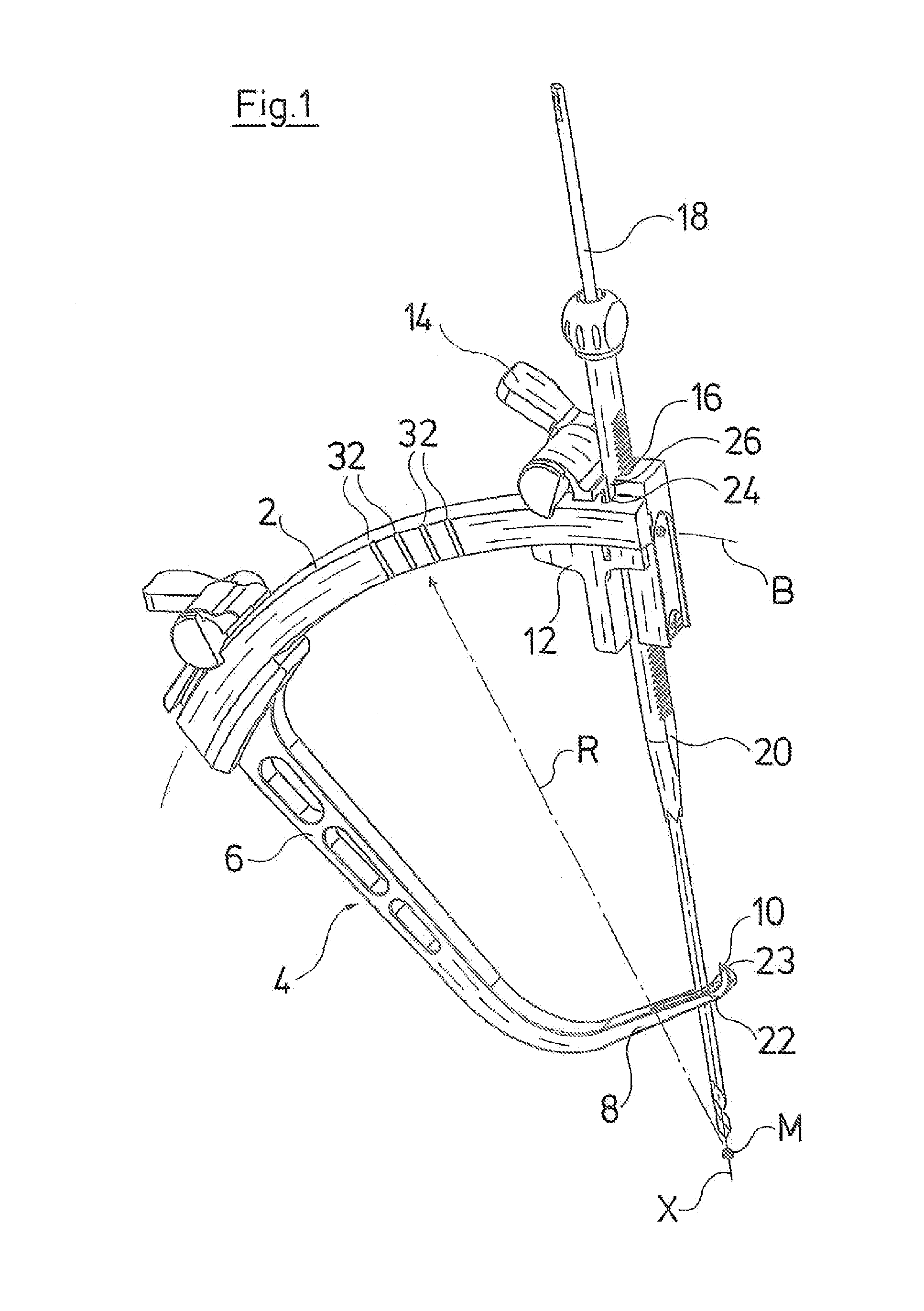
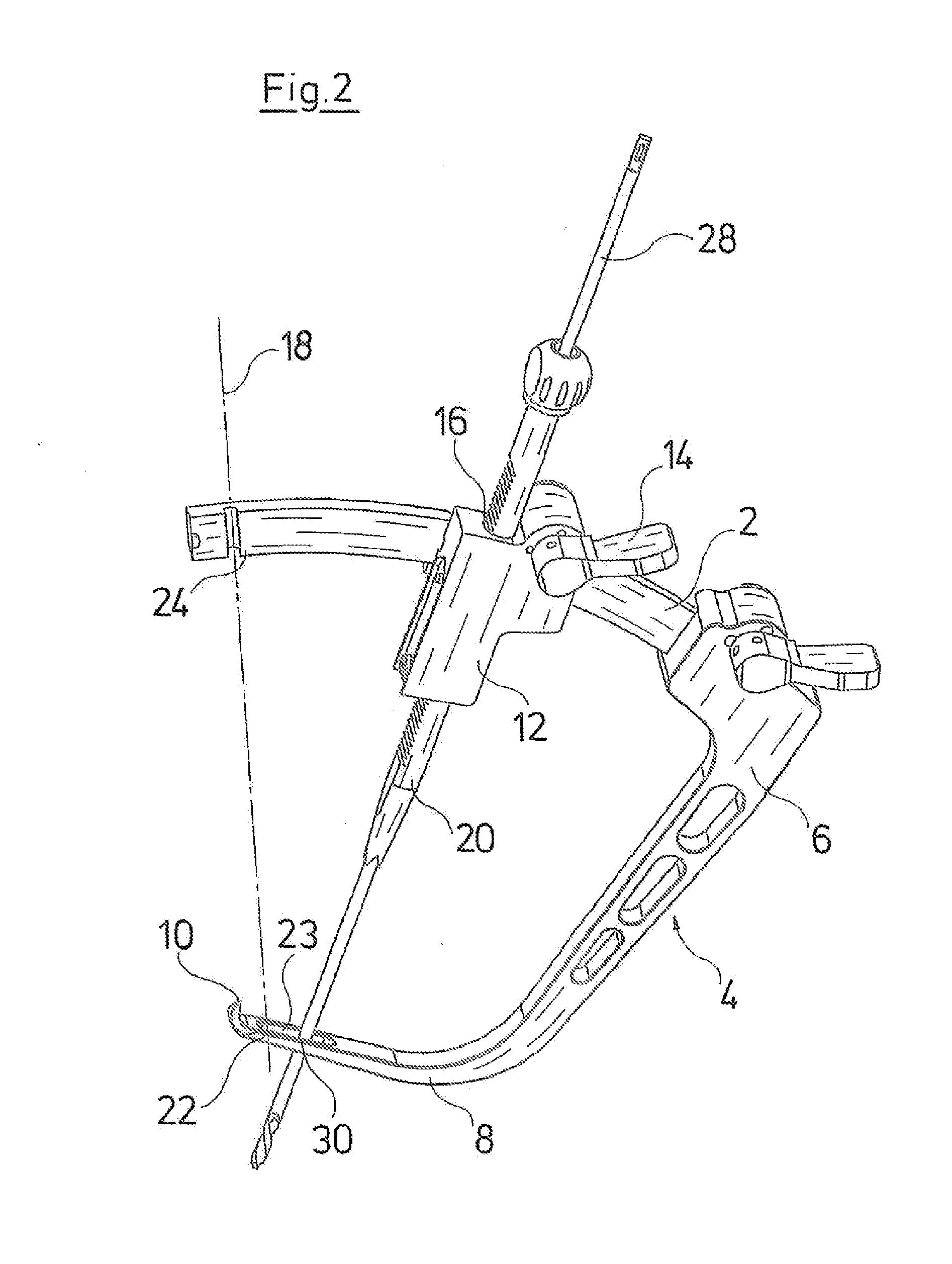
[0033]The guiding device according to the invention shown in the figures has an arc-shaped guide arm 2. This is curved in the form of an arc having radius R about point M. A guide hook 4 is attached, in this case detachably, to one extremity of guide arm 2. Guide hook 4 has a first section 6 that extends outwardly from guide arm 2. This section extends perpendicularly to the longitudinal direction, that is, perpendicularly to the arc described by guide arm 2. A second section 8 is connected to first section 6 and at an angle thereto, the distal end of which second section forms the distal end of guide hook 4, which is constructed as a tip 10 facing toward guide arm 2. Second section 8 of guide hook 4 is angled in a known manner, such that it is able to encircle the bone in which the holes are to be drilled, so that tip 10 may be positioned on the rear of the bone at that point where the drillholes to be created exit the bone. In this way, it is possible to mark the exit sites of the...


PUM


Abstract

A surgical guiding device is provided for reconstruction of the anterior cruciate ligament, including a guide arm and a guide hook extending away from the arm. The guide arm is constructed in the form of an arc, supports a mounting that is slidable on the guide arm and has a fixing device for an alignment wire that is separate from the mounting.

Description

BACKGROUND OF THE INVENTION[0001]The invention relates to a surgical guiding device for reconstruction of the anterior cruciate ligament.[0002]Guiding devices for reconstruction of the anterior cruciate ligament are generally used for positioning and / or aligning drilling channels into a bone, these channels being essential to enable anterior cruciate ligament transplants to be inserted. Depending on the surgical method (single-bundle or double-bundle reconstruction), one or two of these drilling channels are created in the bone. To create these drillholes, first the alignment wires are inserted in the bone with the aid of the guiding device. These are then used later in the operation to guide cannulated drills used to open out the drilling channels to a wider diameter, that is, to the diameter of the anterior cruciate ligament transplants that will subsequently be inserted.[0003]A guiding device for single-bundle reconstruction is known from German published patent application DE 10...

Claims


Application Information

Patent Timeline
IPC IPC(8): A61B17/00
CPCA61B17/1764
Inventor HERDRICH, CHRISTOPFBERG, PETERKORNER, EBERHARDGOTHEL, DIRKSIEBOLD, RAINER
Owner RICHARD WOLF GMBH
Why Eureka
Try Eureka