Hand vacuum cleaner with removable dirt chamber

a vacuum cleaner and dirt collection technology, which is applied in the direction of suction cleaners, cleaning equipment, suction filters, etc., can solve the problems of dirt accumulation in the dirt collection chamber and/or the nozzle of the surface cleaning apparatus, and achieve the effect of simplifying the structur

Active Publication Date: 2011-12-29
OMACHRON INTPROP
View PDF27 Cites 44 Cited by
  • Summary
  • Abstract
  • Description
  • Claims
  • Application Information

AI Technical Summary

Benefits of technology

[0019]A further advantage of this design is that the hand surface cleaning apparatus may have a simplified structure. By providing the nozzle as part of the dirt collection chamber, and preferably as part of a cyclone unit, such an assembly may be removably mounted ...

Problems solved by technology

During operation, dirt may build up in the nozzle of the...

Method used


Image

  • Hand vacuum cleaner with removable dirt chamber
  • Hand vacuum cleaner with removable dirt chamber
  • Hand vacuum cleaner with removable dirt chamber

Examples


Embodiment Construction

[0050]Various apparatuses or methods will be described below to provide an example of each claimed invention. No example described below limits any claimed invention and any claimed invention may cover processes or apparatuses that are not described below. The claimed inventions are not limited to apparatuses or processes having all of the features of any one apparatus or process described below or to features common to multiple or all of the apparatuses described below.

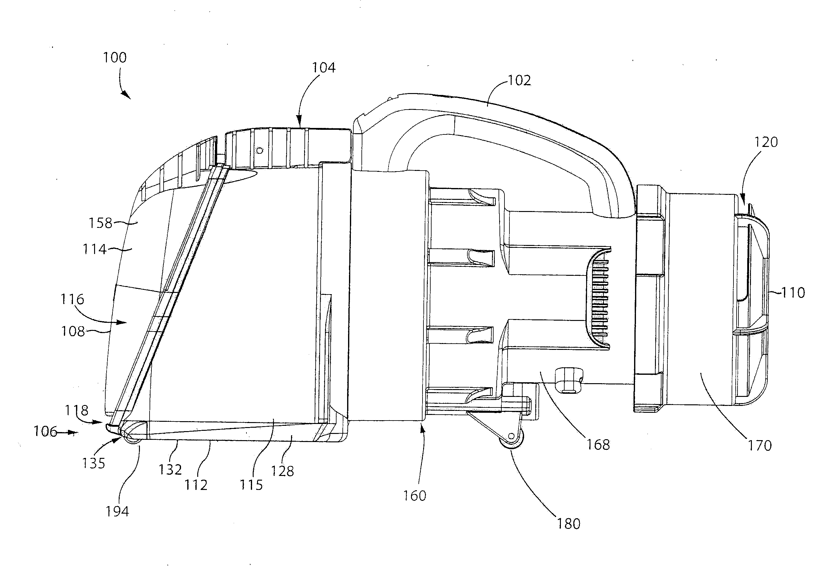
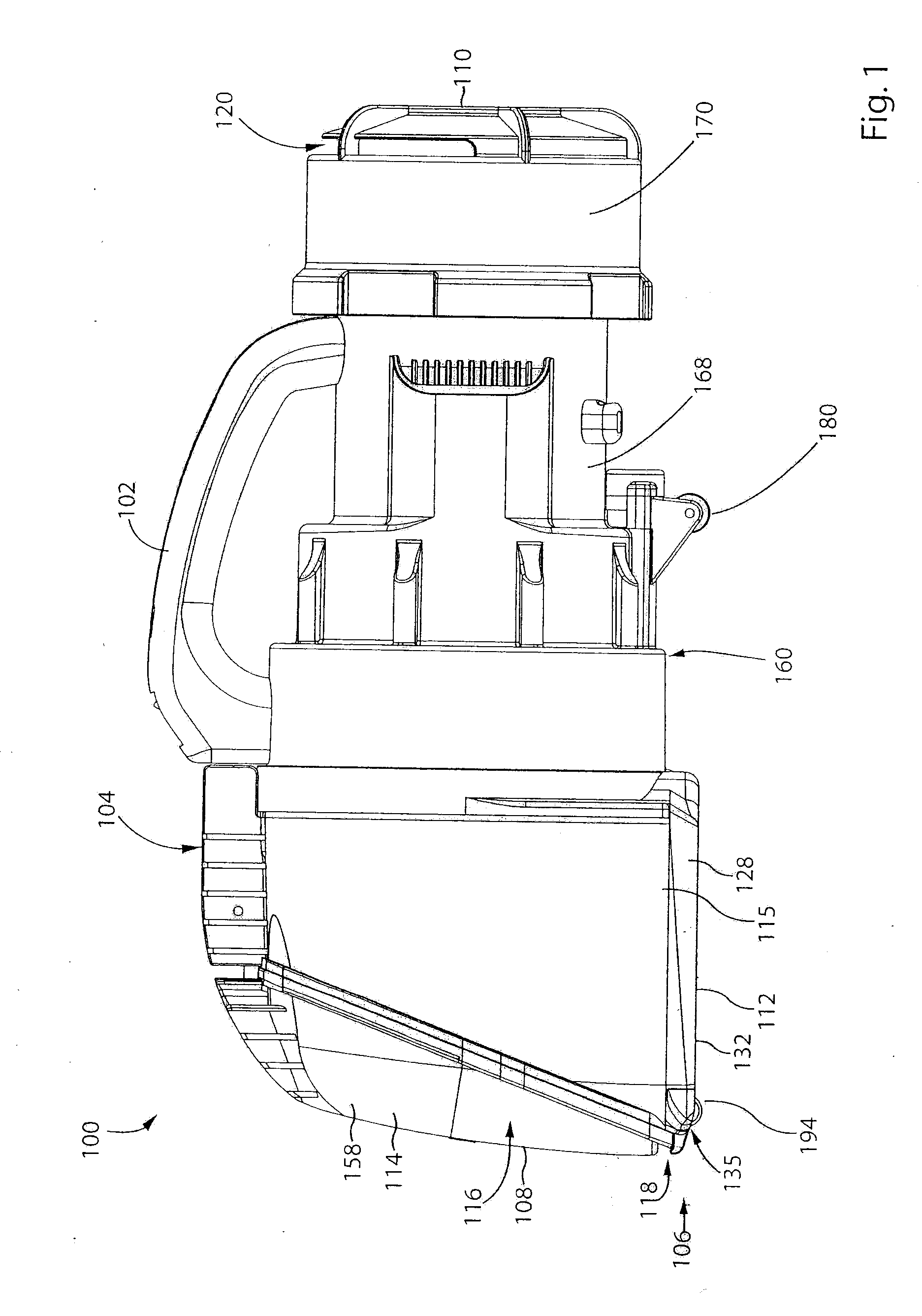
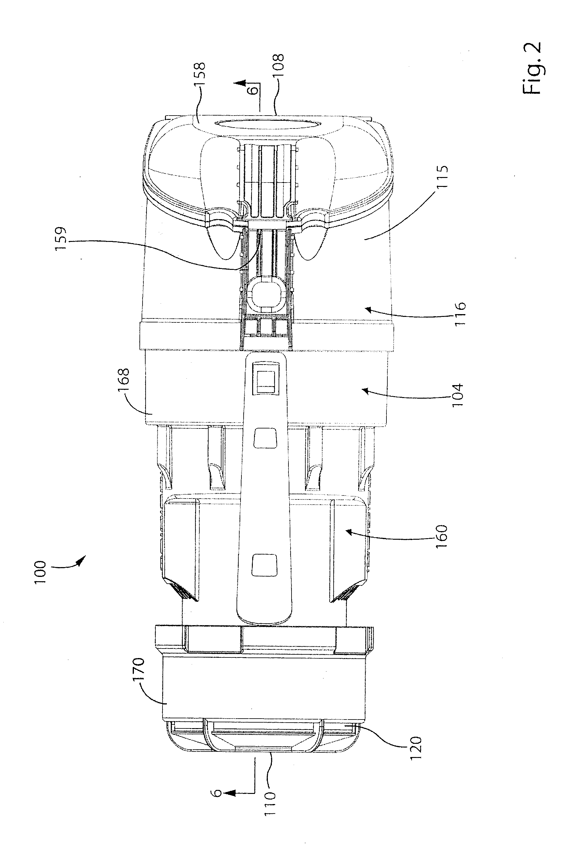
[0051]In the drawings attached hereto, the surface cleaning apparatus is exemplified as used in a hand vacuum cleaner that uses a single cyclone axially aligned with a longitudinal axis of the hand vacuum cleaner. It will be appreciated that the vacuum cleaner 100 may be of various configurations (e.g., different positioning and orientation of the cyclone unit and the suction motor and differing cyclone units that may comprise one or more cyclones and one or more filters) and different types of surface cleaning appar...


PUM


Abstract

A hand surface cleaning apparatus comprises at least one cyclone and at least one dirt collection chamber The dirt collection chamber may be removable from the surface cleaning apparatus as a sealed unit for emptying and/or the dirt collection chamber may be removable with the nozzle.

Description

[0001]The specification relates to hand carried surface cleaning apparatus such as vacuum cleaners, and particularly, to cyclonic hand vacuum cleaners. More specifically, the specification relates to hand vacuum cleaners having a removable dirt chamber.INTRODUCTION[0002]The following is not an admission that anything discussed below is prior art or part of the common general knowledge of persons skilled in the art.[0003]PCT publication WO 2008 / 009890 (Dyson Technology Limited) discloses a handheld cleaning appliance comprising a main body, a dirty air inlet, a clean air outlet and a cyclonic separator for separating dirt and dust from an airflow. The cyclone separator is located in an airflow path leading from the air inlet to the air outlet. The cyclonic separator is arranged in a generally upright orientation (i.e., the air rotates about a generally vertical axis in use). A base surface of the main body and a base surface of the cyclonic separator together form a base surface of t...

Claims


Application Information

Patent Timeline
IPC IPC(8): A47L5/24A47L9/10A47L9/16
CPCA47L5/24A47L9/1691A47L9/106A47L9/00
Inventor CONRAD, WAYNE ERNEST
Owner OMACHRON INTPROP
Why Eureka
Try Eureka