Oil supply system with main pump deaeration

a technology of oil supply system and main pump, which is applied in the direction of engine lubrication, air transportation, jet propulsion plant, etc., can solve the problems of increasing the overall weight of the engine, increasing the quantity of oil needed, and increasing the size of the tank

Active Publication Date: 2011-12-29
PRATT & WHITNEY CANADA CORP
View PDF10 Cites 42 Cited by
  • Summary
  • Abstract
  • Description
  • Claims
  • Application Information

AI Technical Summary

Benefits of technology

[0005]In one aspect, there is provided an oil supply system for supplying oil under pressure to enclosures of a gas turbine engine, the system comprising: a scavenge system in fluid communication with one or more of the enclosures to receive a used oil mixture therefrom; a main oil pump including a first stage and a second stage in serial communication with one another, the first stage including a centrifugal air/oil separator having an inlet in fluid communication with the scavenge system to receive the used oil mixture and separate oil and air contained therein, a main oil outlet located to discharge a major portion of the separated oil therethrough, an oil over

Problems solved by technology

The dwell time of the oil in the tank increases the quantity of oil necessary in the system, and as such the size of the tank required to contain it.
This increases the overall weight of the engine, whic

Method used


Image

  • Oil supply system with main pump deaeration
  • Oil supply system with main pump deaeration
  • Oil supply system with main pump deaeration

Examples


Embodiment Construction

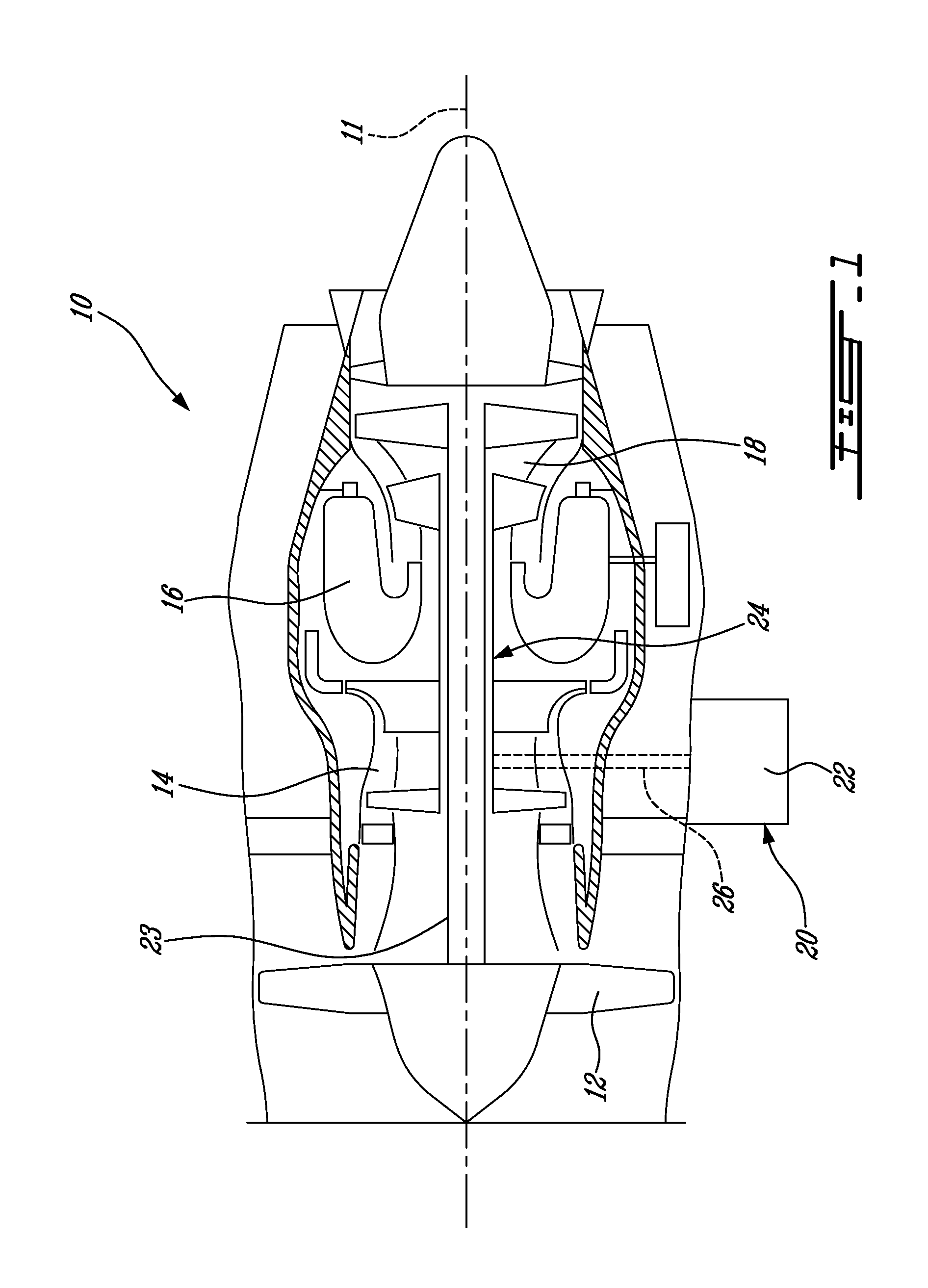
[0012]FIG. 1 illustrates a gas turbine engine 10 of a type preferably provided for use in subsonic flight, generally comprising in serial flow communication a fan 12 through which ambient air is propelled, a compressor section 14 for pressurizing the air, a combustor 16 in which the compressed air is mixed with fuel and ignited for generating an annular stream of hot combustion gases, and a turbine section 18 for extracting energy from the combustion gases.

[0013]The fan 12 is drivingly interconnected to low pressure rotor(s) of the turbine section 18 through a low pressure shaft 23, and the high pressure rotor(s) of the compressor section 14 is / are drivingly connected to high pressure rotor(s) of the turbine section 18 through a high pressure shaft 24 concentrically surrounding the low pressure shaft 23.

[0014]The gas turbine engine includes an accessory drive assembly 20 which includes an accessory gearbox (AGB) 22. Although not shown, the accessory drive assembly 20 can also includ...


PUM


Abstract

An oil supply system for a gas turbine engine with a centrifugal air/oil separator in fluid communication with the scavenge system to receive the used oil mixture and extract oil and air therefrom, a supply pump in serial connection with the main oil outlet of the separator and in fluid communication with the bearing cavities to deliver the oil thereto, an oil tank in fluid communication with the overflow oil outlet of the separator, and at least one make-up pump having an inlet in fluid communication with the tank and having an outlet in fluid communication with the scavenge system.

Description

TECHNICAL FIELD[0001]The application relates generally to gas turbine engines and, more particularly, to oil supply systems for such engines.BACKGROUND OF THE ART[0002]In gas turbine engines, oil supply systems typically circulate the used oil mixture from the various enclosures requiring lubrication, such as the main bearing cavities, to the accessory gearbox cavity to reach the oil tank and / or directly to the oil tank, where the used oil mixture rests for a period of time in order to be sufficiently deaerated for recirculation. The deaerated oil is then typically circulated from the oil tank directly back to the enclosures, while the air separated from the used oil mixture circulates from the tank to the gearbox cavity, where it is vented to the atmosphere after having passing through a centrifugal breather to extract residual oil contained therein. The dwell time of the oil in the tank increases the quantity of oil necessary in the system, and as such the size of the tank require...

Claims


Application Information

Patent Timeline
IPC IPC(8): F02C7/06
CPCF01D25/20Y02T50/671F02C7/06Y02T50/60
Inventor LEGARE, PIERRE-YVES
Owner PRATT & WHITNEY CANADA CORP
Why Eureka
Try Eureka