Capacitive switch

a technology of capacitive switch and switch body, applied in the direction of electronic switching, electrical apparatus, pulse technique, etc., to achieve the effect of increasing interrogation redundancy

Active Publication Date: 2011-12-29
RAFI
View PDF3 Cites 0 Cited by
  • Summary
  • Abstract
  • Description
  • Claims
  • Application Information

AI Technical Summary

Benefits of technology

[0009]It is particularly advantageous when two pairs of sensor surfaces are installed in the printed circuit board and when the two sensor surfaces that form each pair are spaced apart from one another and are arranged in parallel to one of the sensor surfaces of the second pair, because this arrangement significantly increases the in...

Problems solved by technology

If, for example, one of the two integrated circuits on the particular sensor surface does not function correctly, then the microcontroller as the evaluation and control uni...

Method used


Image

  • Capacitive switch
  • Capacitive switch
  • Capacitive switch

Examples


Embodiment Construction

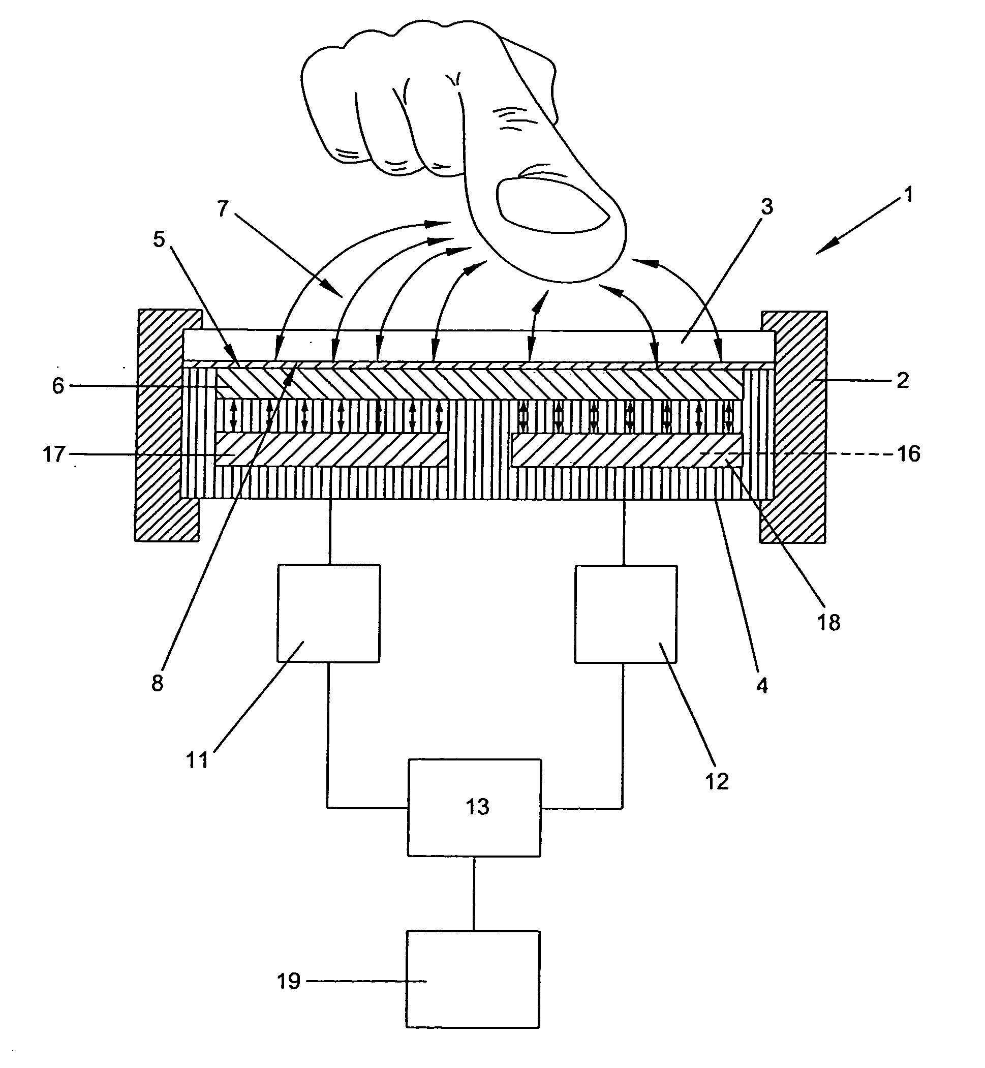
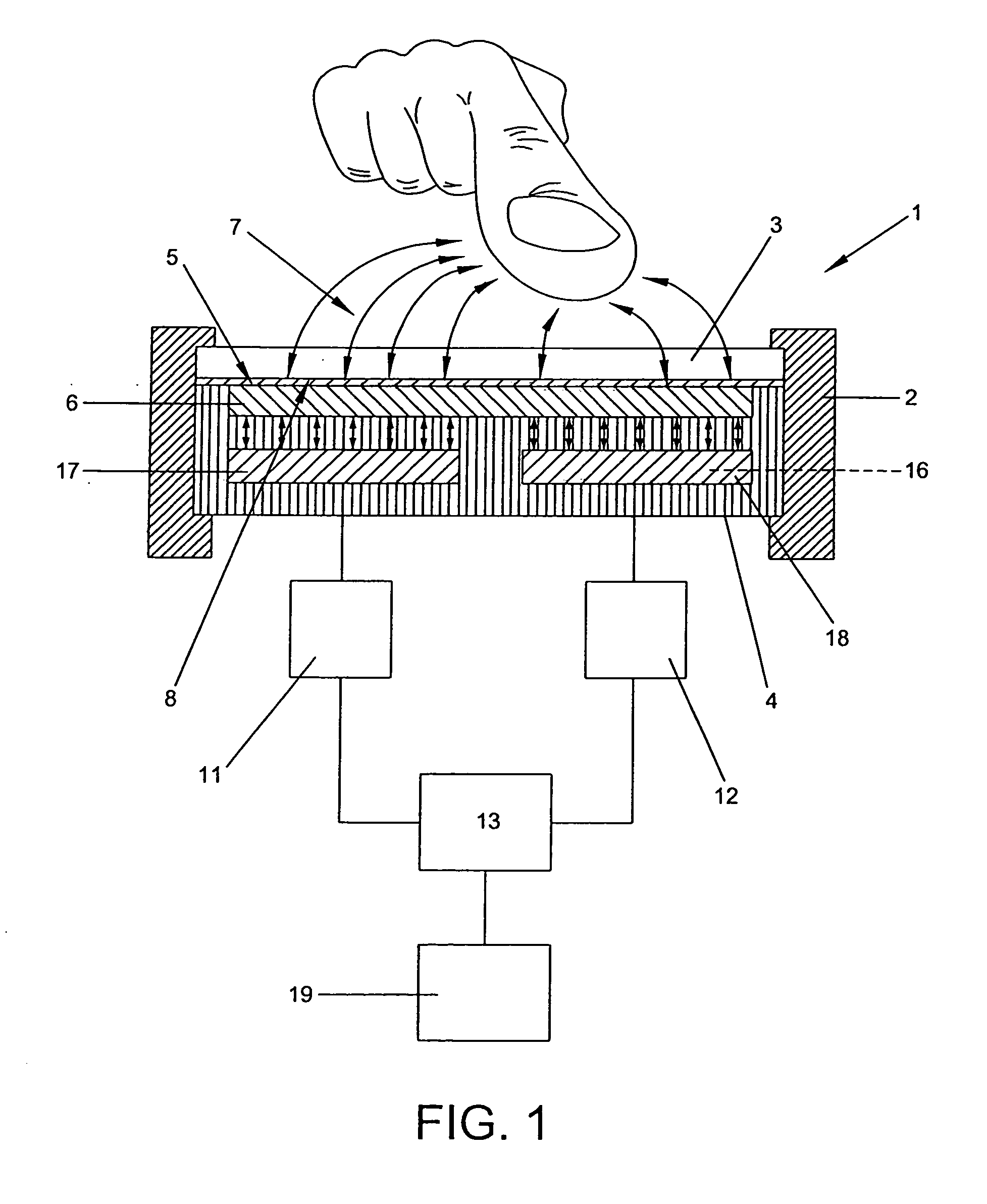
[0017]FIG. 1 shows a capacitive switch 1 which is to be used for controlling an electrical device, for example, as the control unit for a machine tool. In order to check the switching and control function of the capacitive switch 1 in as redundant a way as possible, with the effect that its function corresponds to a specified legal safety standard, the capacitive switch 1 consists of two sensor surfaces 17 and 18 installed in a printed circuit board 4, by means of which a capacitive field 7 generated by a copper layer 6 on the surface 5 of the printed circuit board 4 is picked up, as explained in more detail below.

[0018]The printed circuit board 4 and the copper layer 6 are installed in a housing frame 2. The copper layer 6 is sealed to the outside by means of a thin-walled, transparent or semi-transparent cover plate 3, with the effect that the sensor surfaces 17, 18 arranged under the cover plate 3 are encapsulated with an air-tight seal towards the outside. The sensor surfaces 17...


PUM


Abstract

In a capacitive switch (1) comprising a housing frame (2), a thin-walled cover plate (3) held thereon, a printed circuit board (4) with a copper layer (6) that generates a capacitive field (7) applied to a surface (5) of the circuit board (4) that faces the cover plate (3), the copper layer (6) being connected to an inside surface (8) of the cover plate (3), the capacitive switch (1) being adapted to ensure that electrical devices can be operated safely, in that changes in the capacitive field (7) are picked up by the switch (1) in a redundant manner.
At least two sensor surfaces (17, 17′, 18, 18′) are disposed in the circuit board (4), and are each electrically connected via an integrated circuit (11, 12) to a microcontroller control and evaluation unit, and the printed circuit board (4) functions as an insulation between the copper layer (6) and the sensor surfaces (17, 17′, 18, 18′), and both integrated circuits (11, 12, 11′, 12′) are controlled alternately by the microcontroller (13) for measuring the capacitive field (7) of the copper layer (6).

Description

BACKGROUND OF THE INVENTION[0001]1. Field of the Invention[0002]The invention relates to a capacitive switch of a kind used in a large number of applications. A capacitive field generated by a copper layer radiates in the direction of a user interface. As soon as the capacitive field is disrupted, for example, by being penetrated by a human finger, the field value changes. An integrated circuit arranged adjacent and close to the copper layer permanently measures these changes in the capacitive field, with the effect that an electrical switching signal can be generated by means of a microcontroller that is electrically connected to the integrated circuit when the capacitive field of the copper layer rises above or drops below a preset limit value.[0003]2. Description of the Prior Art[0004]It has proved to be disadvantageous in a capacitive switch of this kind that it cannot be used in electrical devices which have to fulfil a certain safety requirement. For example, false switchings ...

Claims


Application Information

Patent Timeline
IPC IPC(8): H03K17/96
CPCH03K17/962H03K2217/96077
Inventor BULACH, ERIC
Owner RAFI
Why Eureka
Try Eureka